Comparator, analog-to-digital converter and method of analog-to-digital conversion using non-linear magneto-electronic device

a non-linear magneto-electronic device and analog-to-digital converter technology, applied in the field of analog-to-digital converters, can solve the problems of imposing speed and power limits, discharging more power, and relatively low bandwidth and high operating power

Inactive Publication Date: 2004-01-13
THE UNITED STATES OF AMERICA AS REPRESENTED BY THE SECRETARY OF THE NAVY
View PDF8 Cites 10 Cited by
  • Summary
  • Abstract
  • Description
  • Claims
  • Application Information

AI Technical Summary

Benefits of technology

In another embodiment, the write wires through which the input current is applied to the HHE device are electrically isolated from the rest of the device and, in particular, are isolated from device output. Since the input write current is coupled inductively to the device, the capacitance is intrinsically low. It follows that a natural function of the HHE device is that of an electronic isolator. In the existing state of the art, high degrees of electrical isolation are typically provided opto-electronically. This approach is characterized by relatively low bandwidth and high operating power. Because it requires integrated light emitting diodes and photoreceptors, it is also characterized by low density of integration. A single HHE device can provide the isolation function with broad bandwidth. Because a single device is required, integration is high and power is low, and the HHE electrical isolator has significant advantages over the existing art.

Problems solved by technology

These passive components impose limits on speed and power.
Although they have faster conversion rates, they dissipate more power.
This approach is characterized by relatively low bandwidth and high operating power.

Method used


Image

  • Comparator, analog-to-digital converter and method of analog-to-digital conversion using non-linear magneto-electronic device
  • Comparator, analog-to-digital converter and method of analog-to-digital conversion using non-linear magneto-electronic device
  • Comparator, analog-to-digital converter and method of analog-to-digital conversion using non-linear magneto-electronic device

Examples


Embodiment Construction

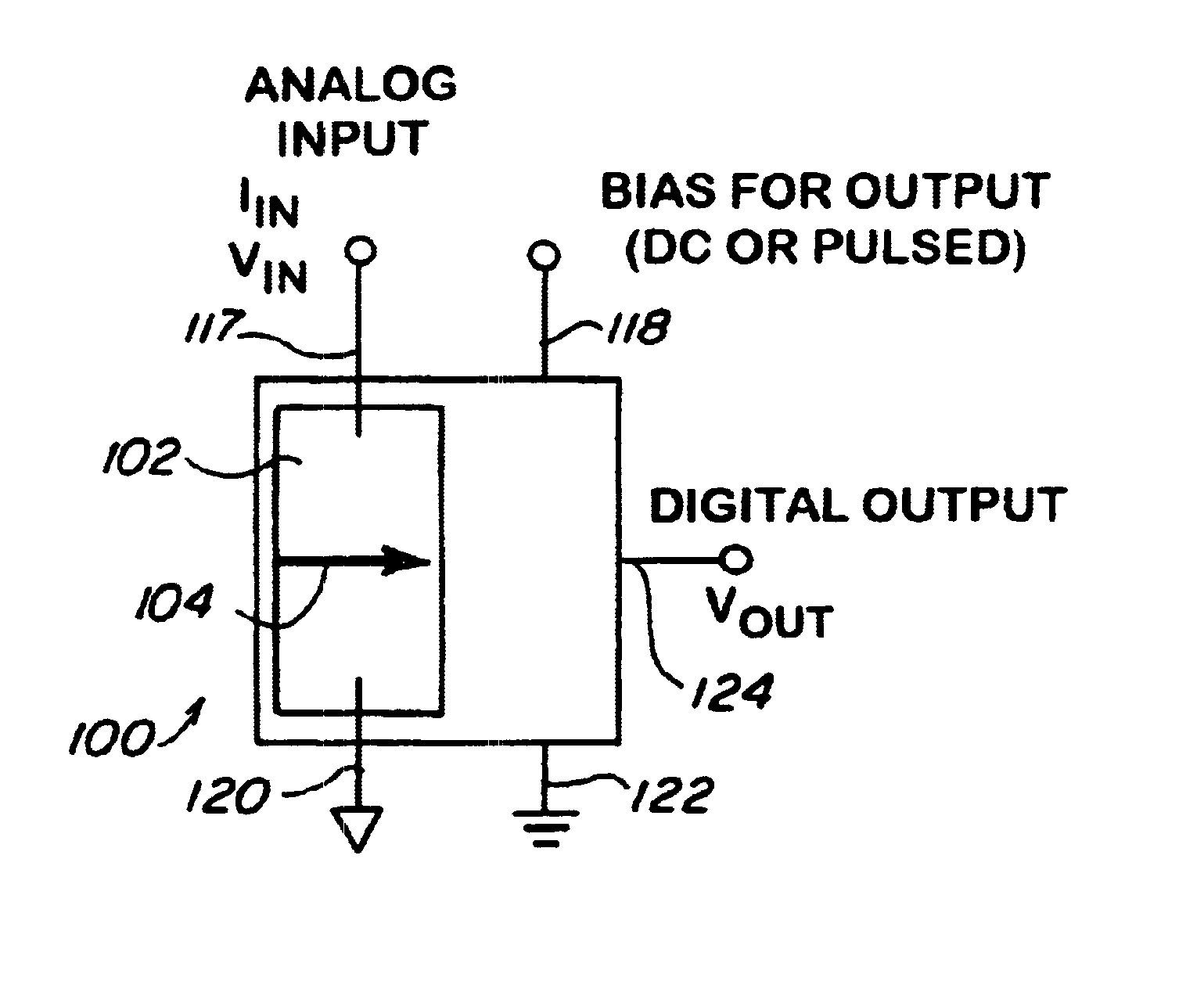
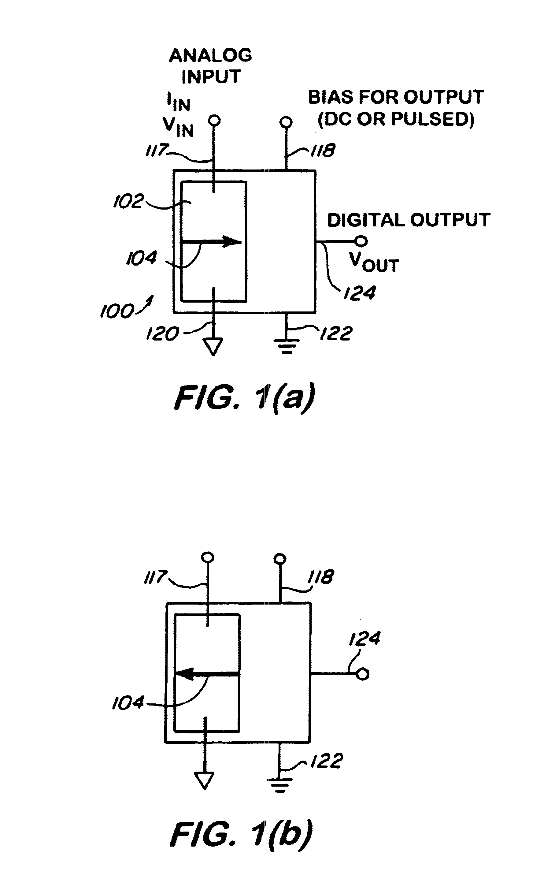
Referring now to FIG. 1a, there is shown a schematic view of a generic magnetoelectronic device 100, defined as a device that incorporates a magnetic element 102 having an output voltage that depends on its magnetization state. Exemplary magnetic elements include spin valves, magnetic tunnel junctions (MTJs), and Hybrid Hall Effect (HHE) devices. The structure of the device 100 may include one or more ferromagnetic elements 102, but the operation of the device 100 typically depends on the manipulation of the magnetization 104 of the ferromagnetic element 102. The magnetization 104 has bistable states, with orientation to the right (positive x, FIG. 1a) or left (negative x, FIG. 1b). Binary information is associated with these bistable orientations. For example, "0" corresponding to left orientation and "1" corresponding to orientation to the right.

The magnetization orientation 104 is controlled by applying current I.sub.IN (or voltage V.sub.IN) to an input terminal of an integrated ...


PUM


Abstract

An analog-to-digital converter for converting an analog input signal to a digital output signal is described. The ADC includes a comparator circuit having first to nstages of comparators responsive to the analog input signal. Each comparator includes a plurality of magnetoelectronic devices for performing comparison function. Each magnetoelectronic device has one or more ferromagnetic elements capable of being switched into a first or second magnetization states. The amplitude of analog input signal upon exceeding a predetermined threshold level (IS or VS) of a respective magnetoelectronic device sets a magnetization state of the respective magnetoelectronic device to the first state and the resulting output of the respective magnetoelectronic device to a HIGH state, and vice-versa. In one embodiment, the magnetoelectronic device is a Hybrid Hall Effect device. In another embodiment, the magnetoelectronic device is an isolator.

Description

1. Field of the InventionThis invention relates to analog-to-digital converters (ADC), and more particularly, to analog-to-digital converters using non-linear magnetoelectronic apparatus to perform comparison function.2. Description of Related ArtHigh speed signal processing, used in numerous applications including telecommunications, involves conversion of analog input signals to digital data streams that are then processed by integrated circuits. The conversion process is typically performed by an analog-to-digital converter (ADC) while the converse process from digital to analog conversion is performed by a digital-to-analog converter (DAC).The growing development of telecommunications applications that rely on bandwidth, in the range of 0.3 to 3 GHz, has generated a strong need for ADCs that operate in this frequency range, and there is an obvious advantage for ADCs that are fabricated at low cost while operating with low power. For instance, cellular phones typically operate at...

Claims


Application Information

Patent Timeline
Patent Type & Authority Patents(United States)
IPC IPC(8): H03K5/24H03K5/22H03M1/36H03M1/08
CPCH03K5/24H03M1/361H03M1/368H03M1/0827
Inventor JOHNSON, MARK B.STAPOR, BILL
Owner THE UNITED STATES OF AMERICA AS REPRESENTED BY THE SECRETARY OF THE NAVY
Why Eureka
Try Eureka