Tunable antenna system

a technology of antenna system and antenna array, which is applied in the field of radio antennas, can solve the problems of inability to optimally tune, large and complex array of antenna designs, and inability to achieve wide frequency coverag

Inactive Publication Date: 2004-01-13
STEPPIR COMM SYST INC
View PDF14 Cites 39 Cited by
  • Summary
  • Abstract
  • Description
  • Claims
  • Application Information

AI Technical Summary

Benefits of technology

It is a further object of the present invention to provide such an antenna system that is easy to assemble and dismantle.
The antenna system also includes a radio system that is connected to the driven element on the antenna. The antenna system may have one or more parasitic elements. The system also includes an electronic control unit that controls the length of the conductive member in each element on the antenna which allows the operator to select a desired frequency, read the operating frequency of the radio, adjust the antenna manually or automatically or measure the transmit frequency with a frequency counter, and then adjust the antenna automatically. In a second embodiment, both support arms are telescopic and adjustable in length. The distal ends of the conductive members are attached to the distal ends of the support arms so that the overall size of the antenna may be adjusted when a desired frequency is received.
The above antenna system is especially advantageous when configured as a Yagi-style antenna that can be optimally tuned at a specific frequency for maximum gain, maximum front-to-back ratio, and to provide a desired feed point impedance at the driven element. This allows a very large continuous range of frequencies to be covered with excellent performance and a very low voltage-standing-wave-ratio (VSWR) while using only one feed line. By using length adjustable elements and a shorter boom, the antenna system is able to achieve better performance than prior art antenna designs. Also incorporated into it is a Yagi-style antenna, enabling it to be quickly adjusted to change the direction of maximum signal strength 180 degrees by changing the length of the designated director to make it function as a reflector and conversely changing the length of the reflector to make it function as a director. In should also be understood that the antenna system can also function as a bi-directional style antenna by adjusting the reflector element to function as a director.

Problems solved by technology

Unfortunately, resonant antennas by their nature operate over a very narrow range of frequencies.
Some prior art antenna designs address multiple bands that cover three of the aforementioned bands, and in some cases five bands, but with very compromised performance.
To provide even marginal performance, these antenna designs require large and complex arrays.
Although multi-element trapped antennas cover multiple frequencies with fewer elements than others designs, they cannot be optimally tuned and there are significant losses associated with traps in all of the elements including the driven element.
However, the open-sleeve technique only applies to a driven element.

Method used


Image

  • Tunable antenna system
  • Tunable antenna system
  • Tunable antenna system

Examples


first embodiment

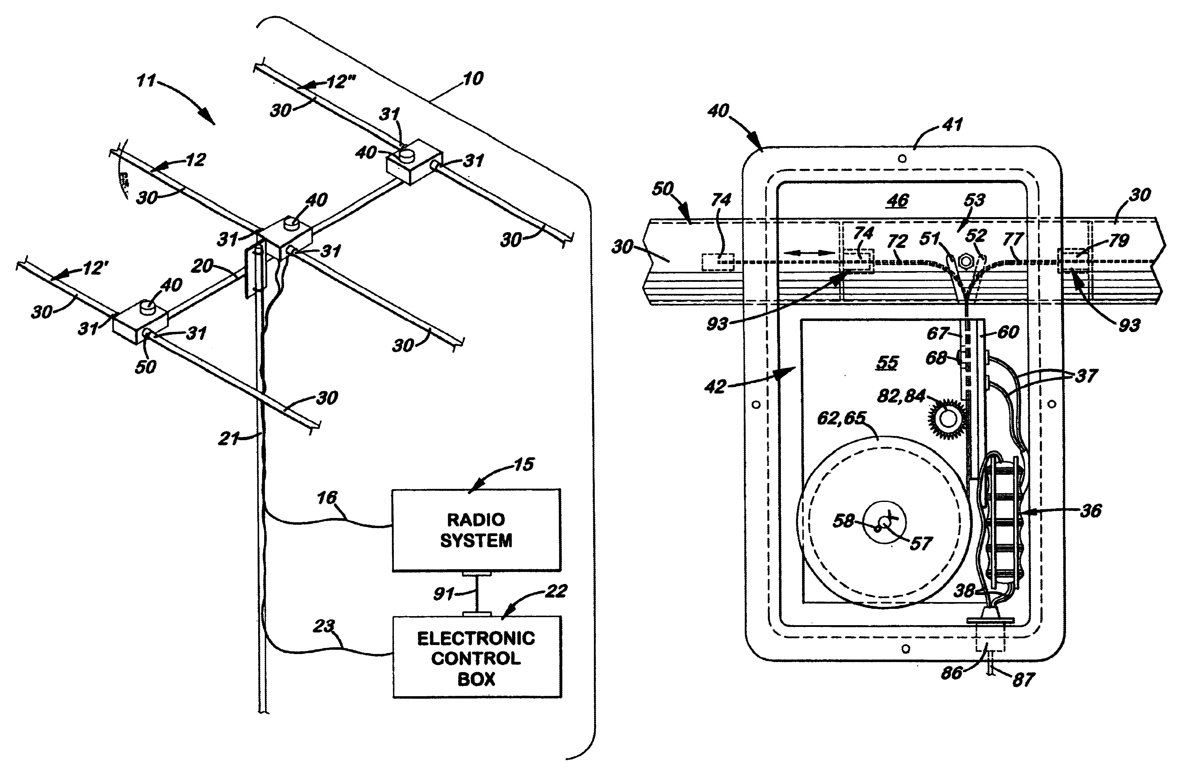
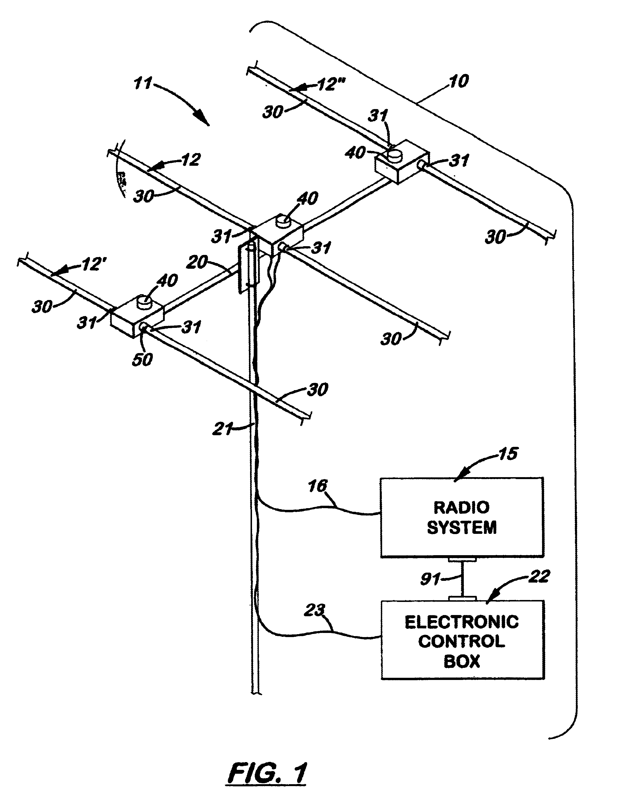
FIG. 8 is a block diagram of the antenna system 10. The motherboard 27 with programmable logic array 28, under the direction of the software program 29, controls the operation of all three elements 12, 12', 12" simultaneously via stepper motor drivers 83, 83', 83", respectively. The display 24 indicates various operating parameters such as current frequency, mode, warning messages, setup data for RS-232 communications, antenna creation data, and calibration data. The keyboard / LED component 26 allows the human operator to change bands, change modes, create and save antennas, and perform calibrations. The keyboard / LED peripheral component 26 provides indications of various functions such as band indication, mode selection, and sundry functions. The software program 29 either calculates the required lengths of antenna elements 12, 12', 12" from formulas or uses lookup tables depending on the mode of operation. The user can also customize the antenna 11 to satisfy specific requirements ...

second embodiment

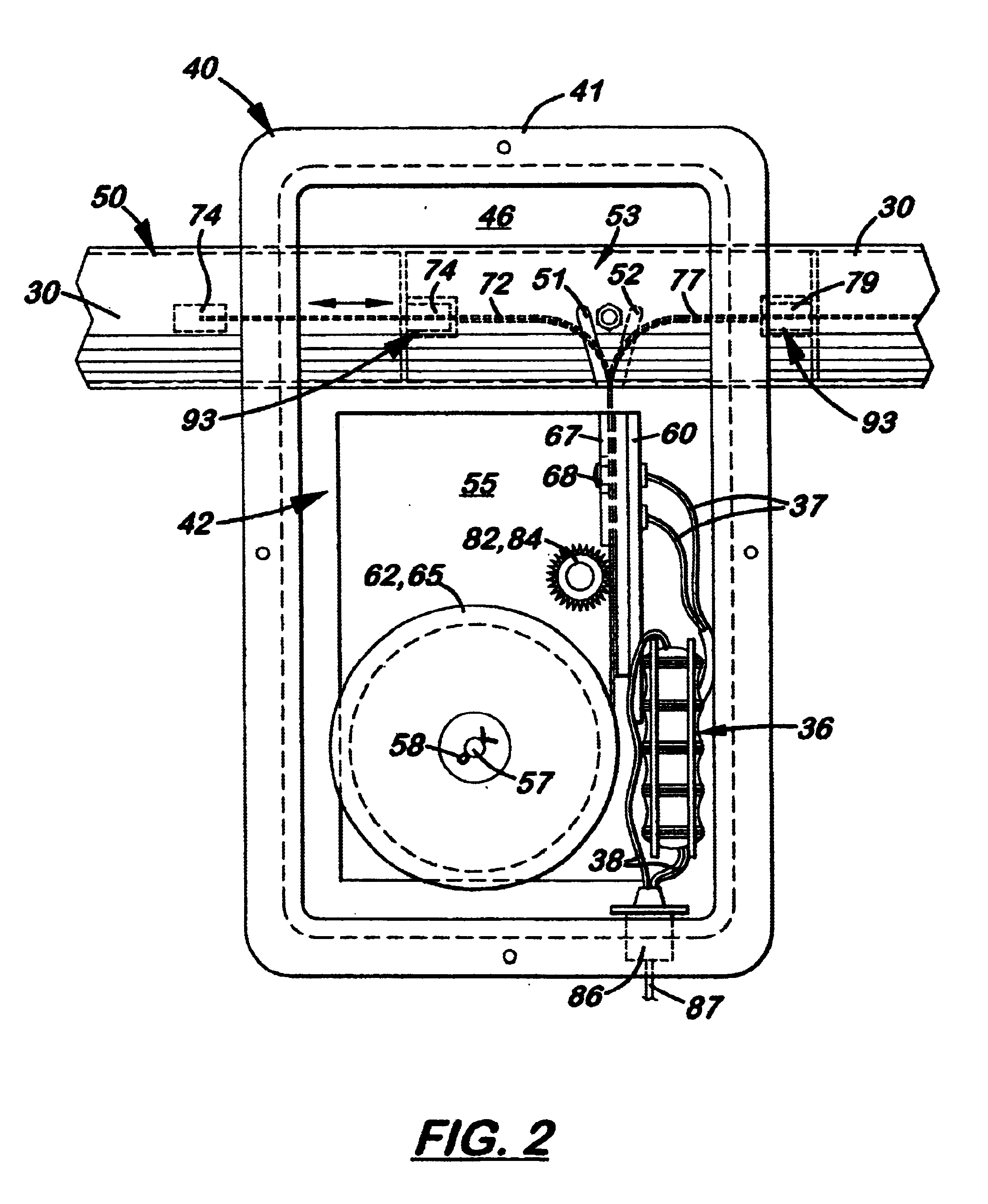
In a second embodiment, shown in FIG. 6, the support arms 30 are telescopically designed to adjust in length to the length of the conductive member 72, 77. In the preferred embodiment, there are four 4-foot sections 32-35, each slightly smaller than the other so that the sections 32-35 may be longitudinally aligned and telescopically adjusted in length. Attached to the distal end of the last section 35 is a non-conductive cap 39 that attaches to the distal end of the conductive member 72 (shown) or 77 (not shown). When the conductive member 72, 77 is moved inside the support arm 30, the sections 32-35 telescopically move so that the overall length of the support arm 30 is approximately equal to the length of the conductive member 72, 77.

During operation, the operator may use the electronic control unit 22 to perform some of the following functions:

1. Single button band selection includes the ability to scroll through the band in segments of approximately 100 kHz.

2. Continuous adjust...


PUM


Abstract

An antenna system with at least one tunable dipole element with a length adjustable conductive member disposed therein that enables the antenna to be used over a wide range of frequencies. The element is made of two longitudinally aligned, hollow support arms made of non-conductive material. Disposed longitudinally inside each element is a length adjustable conductive member electrically connected at one end. In the preferred embodiment, each conductive member is stored on a spool that is selectively rotated to precisely extend the conductive member into the support arm. The support arms, which may be fixed or adjustable in length, are affixed at one end to a rigid housing. During use, the conductive members are adjusted in length to tune the element to a desired frequency. The antenna is especially advantageous when configured as a Yagi-style antenna that can be optimally tuned at a specific frequency for maximum gain, maximum front-to-back ratio, and to provide a desired feed point impedance at the driven element. The antenna can also function as a bi-directional antenna by adjusting the reflector element to function as a director. An electronic control system allows the length of the conductive members to be manually or automatically adjusted to a desired frequency.

Description

1. Field of the InventionThe present invention relates to the field of radio antennas, and more particularly, to wide frequency coverage vertical, dipole and parasitic array antennas.2. Description of the Related ArtIt is often desired to provide a single antenna having excellent performance over a wide frequency range. In the interest of efficiency and impedance matching, antennas used for radio communication are generally resonant antennas. Unfortunately, resonant antennas by their nature operate over a very narrow range of frequencies. To be resonant at a specific frequency, the antenna must be a certain specific length.Three commonly used resonant antennas are the dipole, vertical and Yagi-Uda. A dipole antenna is comprised of a single element, usually one half of a wavelength long at the design frequency. It is then usually split at the center where electromagnetic energy is then fed. Vertical antennas are basically dipoles oriented in a vertical plane with one half of the elem...

Claims


Application Information

Patent Timeline
Patent Type & Authority Patents(United States)
IPC IPC(8): H01Q19/30H01Q19/00
CPCH01Q1/10H01Q9/14H01Q19/30
Inventor MERTEL, MICHAEL E.
Owner STEPPIR COMM SYST INC
Why Eureka
Try Eureka