Method of refrigeration with enhanced cooling capacity and efficiency

a technology of refrigeration and efficiency, applied in the field of refrigeration methods, can solve the problems of cfcs environmental risks, best substitutes present long-term risks, and offer a control method, so as to improve the efficiency of transcritical vapor compression refrigeration cycles and increase their capacity

Inactive Publication Date: 2004-03-02
THAR PROCESS
View PDF4 Cites 36 Cited by
  • Summary
  • Abstract
  • Description
  • Claims
  • Application Information

AI Technical Summary

Benefits of technology

It is therefore an object of the present invention to improve the efficiency of the transcritical vapor compression refrigeration cycles and to increase their capacity.
Another object of the present invention is to simplify the refrigeration process by avoiding the need for an accumulator that is otherwise employed for the purpose of providing a buffer for handling varying amounts of liquid-state working fluid in the system.
Another object of the present invention is to operate the refrigeration cycle with an oil-free working fluid and thereby simplify the refrigeration process by avoiding the need for an accumulator that is otherwise employed for the purpose of separating oil from the working fluid.
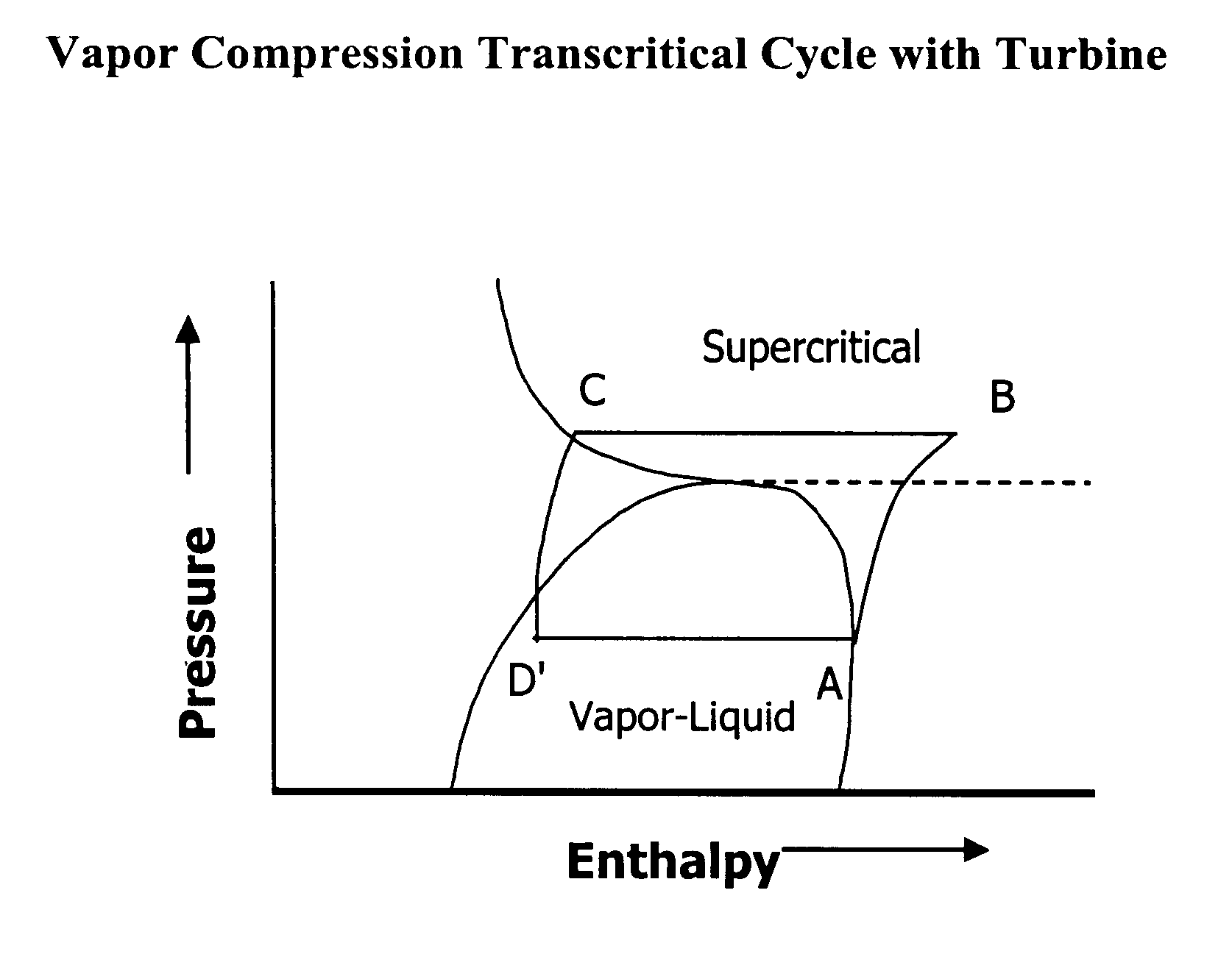
Another object of the present invention is to improve the efficiency of supercritical fluid refrigeration cycles over that of CFC refrigerants by operating the expansion and compression steps in such ways as to reduce thermodynamic irreversibitities. This includes the replacement of an expansion valve with a turbine for expansion, or the use of multi-stage compression, or a combination thereof.
Yet another object of this invention is to improve efficiency using a nontoxic and environmentally benign working fluid.
In further aspects of this invention, said refrigerant is expanded isentropically, thereby increasing capacity and efficiency. One or more intercoolers transfer useful heat from the high pressure side and to the low pressure side. One or more separators are used to separate gas and liquid. A combination of intercoolers and separators are used to transfer useful work from the high pressure side to the low pressure side and to separate gas and liquid. The oil-free refrigerant increases the efficiency of the cycle. Control of the mass flow rate is accomplished through control of compressor. The mass flow rate is controlled by one or more of the following means: varying the inlet mass flow to the compressor, changing the compression stroke, changing the final compression volume or changing the speed of the compressor drive.

Problems solved by technology

In the early 1970s, however, the environmental risks posed by CFCs were realized.
Nevertheless, even the best substitutes present a long-term risk, and the search is on for a refrigerant that has no ozone-depletion potential.
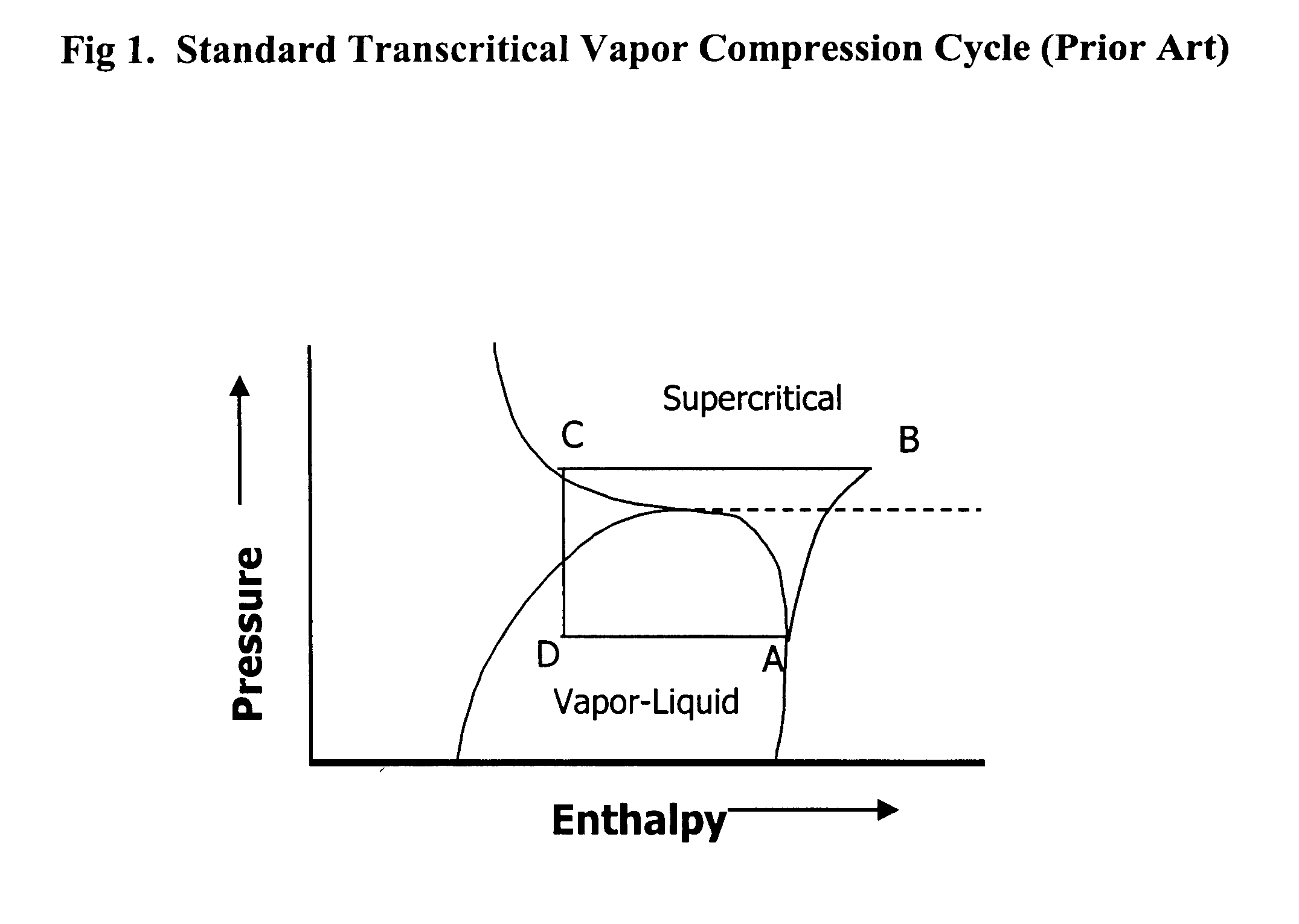
Brenan did not, however, offer a method for controlling the process, nor did he address methods to improve the thermodynamic efficiency of compression or expansion, the points at which the greatest extent of thermodynamic irreversibility take place.
The presence of compressor oil in the working fluid is a disadvantage, the means of separating the oil from the working fluid notwithstanding, because the heat transfer coefficient of the working fluid is decreased by the presence of the oil, thereby reducing overall efficiency.
Such methods are undeveloped in current practice.
The current state-of-the-art, however, has yet to implement all the means possible to achieve highest efficiency.
Most significantly, little has been done to improve compressor efficiency.
Such a system, however, is highly constrained in terms of the range of operating temperatures and portability.

Method used


Image

  • Method of refrigeration with enhanced cooling capacity and efficiency
  • Method of refrigeration with enhanced cooling capacity and efficiency
  • Method of refrigeration with enhanced cooling capacity and efficiency

Examples


example 2

The COP of a cycle operating with a turbine and no intercooler can be improved more than two times, from 2.93 to 6.15, by allowing the temperature at the evaporator inlet (or turbine outlet) to rise from 5.degree. C. to 25.degree. C.

Under practical circumstances, however, the turbine is not expected to operate at 100% isentropic efficiency. Efficiency is in a range of 60% to 85% for impulse turbines, and 60% to 90% for reaction turbines. COP for a cycle operating with an impulse turbine at 85% efficiency is approximately 30-40% higher than the standard cycle and 1-2% more for a reaction turbine.

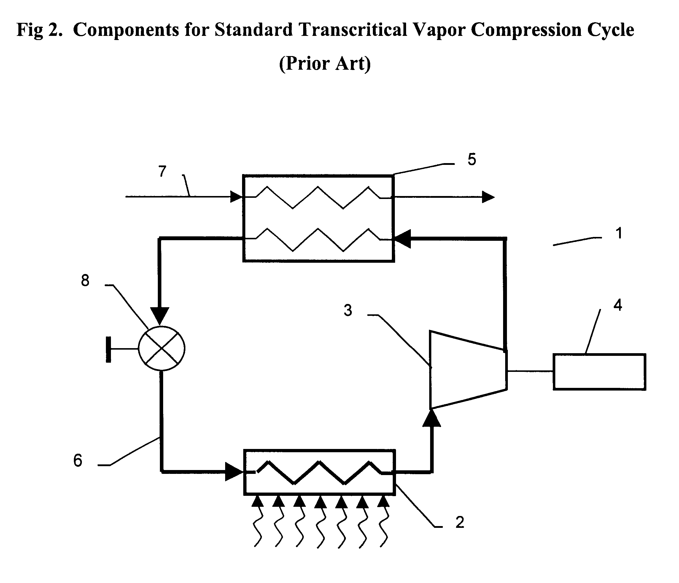
FIG. 4 depicts the components of a system (9) operating according to the cycle shown in FIG. 3. Working fluid (6) exits the heat absorber and enters the suction of the compressor (3) which is driven by motor (4) and which can receive supplementary power by coupling (11), although the use of said coupling is not a requirement of the invention. The fluid then moves in similar manner as in the s...


PUM


Abstract

This invention relates to a refrigeration method and processes that employ a nontoxic and environmentally benign, oil-free refrigerant in a novel vapor-compression thermodynamic cycle that includes a means for enhancing cooling capacity and efficiency. A means of controlling of the process conditions and flow of the refrigerant are provided. The refrigerant in the invention in used in a transcritical cycle.

Description

1. Field of the InventionThis invention relates to a refrigeration method that employs a process or processes, whereby a supercritical fluid is used in a vapor-compression thermodynamic cycle, and more particularly to a means of enhancing cooling capacity and efficiency.2. BackgroundIn conventional vapor-compression refrigeration cycles, heat is absorbed at a constant temperature by a fluid undergoing evaporation, vapor is then compressed to a higher pressure before giving up heat of evaporation, as well as work energy added during compression, in a condenser at a subcritical pressure, before ultimately decompressing through an expander and returning to the evaporator to pick up heat and begin the cycle anew. An alternative to this cycle is to compress the fluid to a supercritical state at a high enough pressure to ensure that it remains in a supercritical state as it releases heat to a cooling medium. In refrigeration cycles, the cooling medium is usually air, but it can be another...

Claims


Application Information

Patent Timeline
Patent Type & Authority Patents(United States)
IPC IPC(8): F25B11/02F25B9/00F25B49/02
CPCF25B9/008F25B11/02F25B49/022F25B2309/061F25B2600/02
Inventor CHORDIA, LALIT
Owner THAR PROCESS
Why Eureka
Try Eureka