Method for production of heat exchanger

a heat exchanger and production method technology, applied in the direction of manufacturing tools, soldering devices, light and heating equipment, etc., can solve the problems of inferior form method and formation of through holes, and achieve excellent corrosion resistance

Inactive Publication Date: 2004-03-23
MITSUBISHI ALUMINUM CO LTD
View PDF23 Cites 26 Cited by
  • Summary
  • Abstract
  • Description
  • Claims
  • Application Information

AI Technical Summary

Benefits of technology

The present invention has been completed in view of the above-mentioned situation. The object of this invention is to provide a method for production of a heat exchanger in which the tubes and the header are strongly bonded to each other and which has excellent corrosion resistance.
According to the heat exchanger produced by this invention, the brazing filler metal layer formed on the header allows the fillets of the brazing filler metal to be sufficiently formed at the joints with the tubes, and the Zn in the thermally Zn-sprayed layer diffuses quickly to average the Zn concentration. As a result, it is prevented that local corrosion takes place at the joints, to form through holes. Furthermore, the brazing filler metal layer formed on the thermally Zn-sprayed layer of the tubes contributes to the bonding with fins, and promotes the diffusion of Zn in the thermally Zn-sprayed layer, for uniforming the Zn concentration on the surfaces of the tubes as an action to enhance corrosion resistance. Moreover, Zn diffuses also into the brazing filler metal of the header, to improve the corrosion resistance at the joints.
The process for producing a heat exchanger as the subject matter of claim 1 can provide the above-mentioned action and effect, and since the prepared powdery brazing filler metal is classified for use, there is also an effect that the powdery brazing filler metal can be used without waste.
The thermally Zn-sprayed layer of the tubes prevents that the Si of the brazing filler metal erodes the base metal, to form through holes, and hence corrosion resistance is also improved. It is preferred that the thermally sprayed amount of the thermally Zn-sprayed layer is in a range of 3 to 20 g / m.sup.2 (a further preferred range is 7 to 15 g / m.sup.2), for the reasons described below. If the thermally sprayed amount of Zn is less than 3 g / m.sup.2, the Zn concentration on the surface of the covering layer is too small to obtain a desired action. On the other hand, if the thermally sprayed amount of Zn is more than 20 g / m.sup.2, a large amount of Zn in the covering layer migrates into the fillets after brazing. So, the fillets are preferentially corroded causing the tubes to be disconnected from the fins, or to cause corrosion at the joints between the tubes and the header, or to raise the Zn concentration of the covering layer, remarkably increasing the corrosion rate.

Problems solved by technology

Of the above-mentioned assembling methods, the former method is inferior since the bondability between the tubes and the header is not sufficient, depending on the brazing filler metal layer of the header.
However, in the latter method, in the case where the thermally Zn-sprayed layer is formed on the surface of the tube, a layer having Zn at a high concentration is kept formed at the joint with the header in the longitudinal direction of the tube 10 as shown in FIG. 2, and corrosion 13 preferentially takes place in the layer, to pose a problem that it causes a through hole to be formed at the joint 12 between the tube 10 and the header 11.

Method used


Image

  • Method for production of heat exchanger
  • Method for production of heat exchanger
  • Method for production of heat exchanger

Examples


example 1

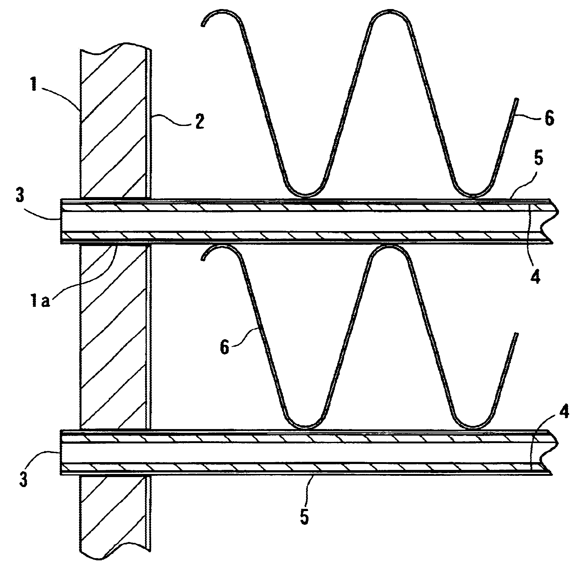
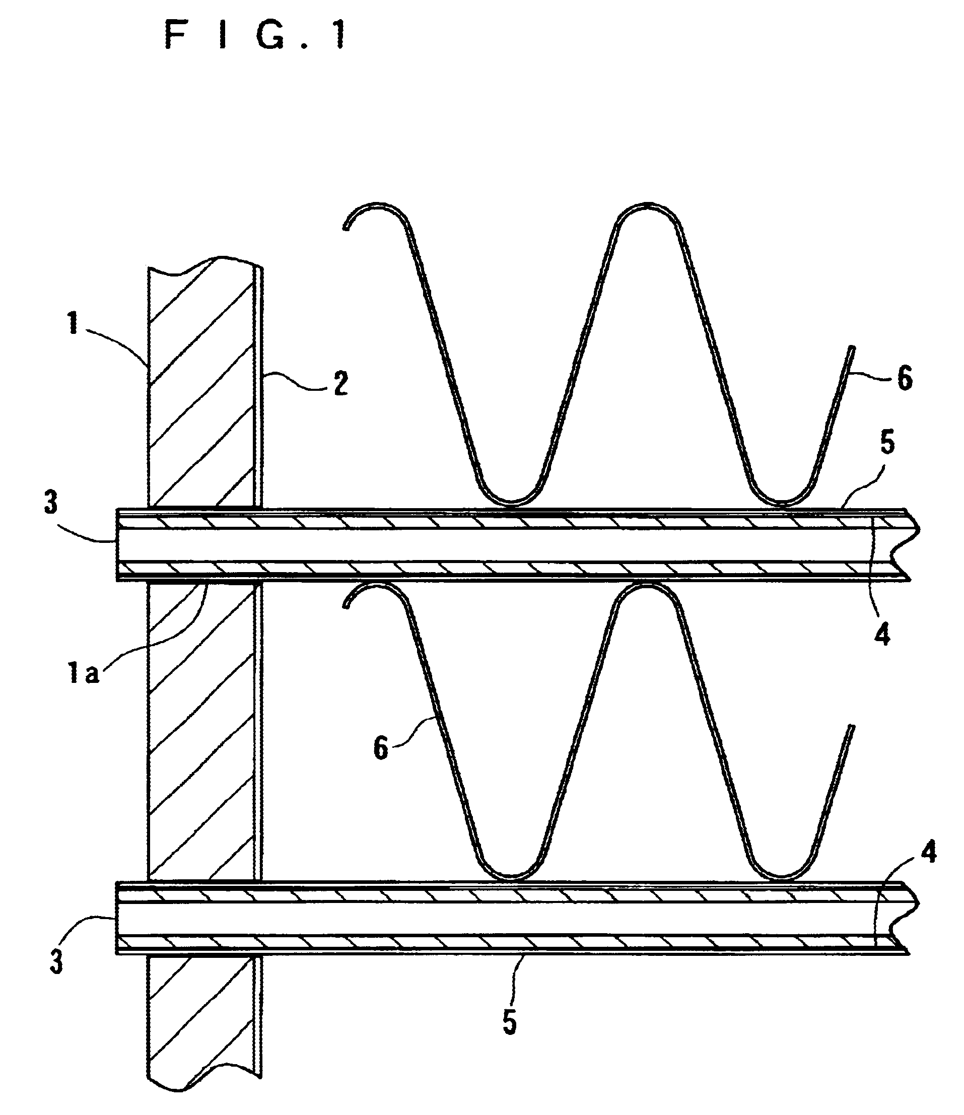
A ingot made of JIS A 1070 Al alloy was extruded to obtain extruded tubes, and Zn was thermally sprayed to the extruded Al alloy tubes immediately after molding, to prepare Zn-covered Al alloy tubes having a thermally Zn-sprayed layer by 10 g / m.sup.2 on the surfaces of the tubes. On the other hand, a header made of JIS A 3003 Al alloy with openings for allowing insertion of the tubes was prepared by means of extrusion molding, and furthermore corrugated fins made of JIS A 3003 Al alloy were prepared.

Moreover, one part by weight of a flux and one part by weight of a binder were mixed with 10 parts by weight of Al-12% Si binary alloy powder with an average particle size of 20 .mu.m obtained by atomizing a molten Al alloy, to prepare a brazing filler metal slurry. Said thermally Zn-sprayed Al alloy tubes were coated with the brazing filler metal slurry by 50 g / m.sup.2, to prepare thermally Zn-sprayed extruded tubes of this invention. As a comparative example, thermally Zn-sprayed extru...

example 2

Thermally Zn-sprayed extruded tubes and a header were coated with a brazing filler metal to produce heat exchangers as described for Example 1, except that the powdery brazing filler metal of the brazing filler metal slurry in Example 1 was sieved for classification into various divisions different in average particle size.

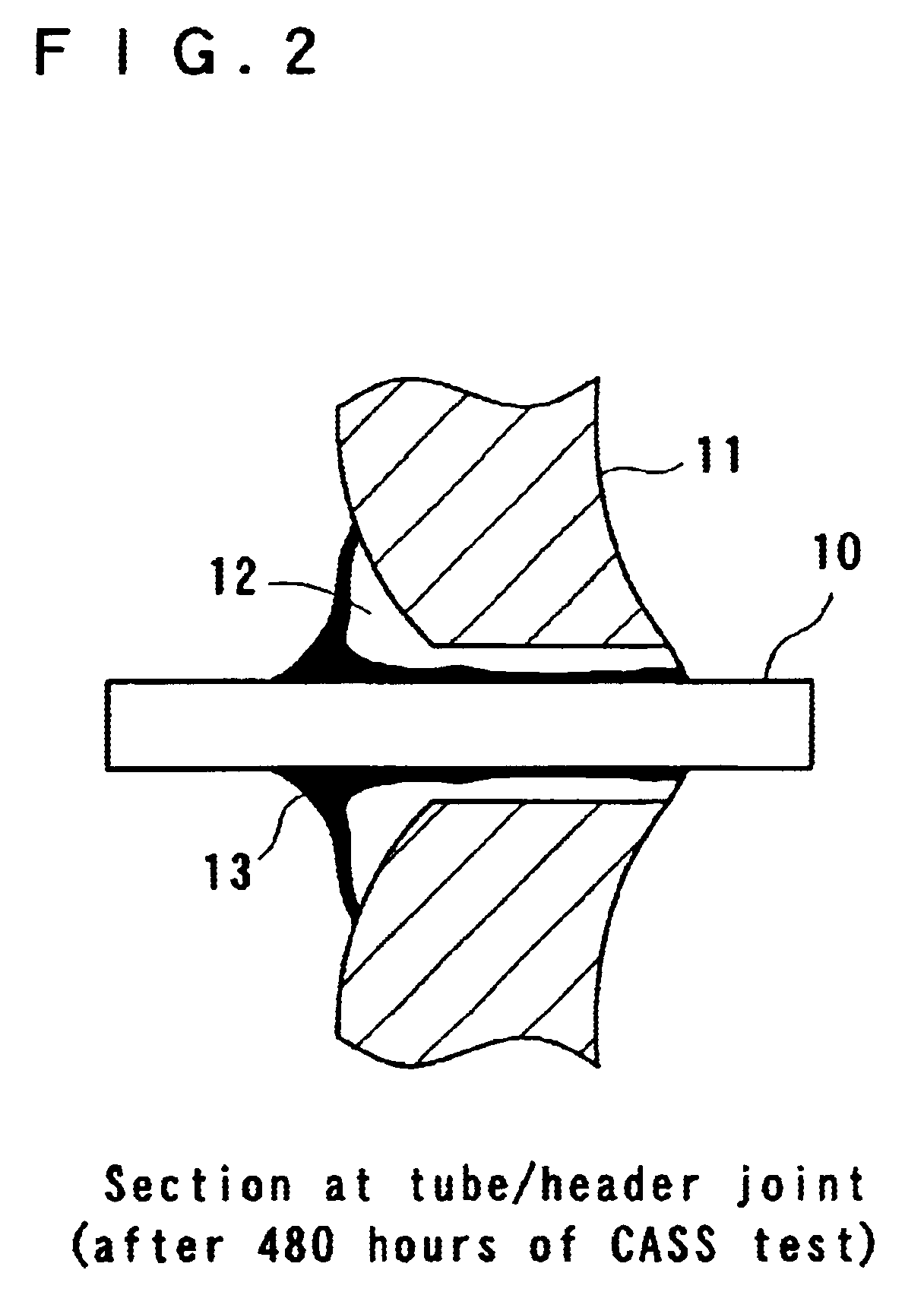
For the obtained heat exchangers, the brazing property at the tube / header joints was evaluated. For the brazing property, a case where the clearances at the joints could be perfectly filled with the brazing filler metal is expressed by ".smallcircle.", and a case where the clearances were filled imperfectly is expressed by ".quadrature.". The results are shown in Table 2.

As can be seen from Table 2, in the cases where the average particle size of the powdery brazing filler metal applied to the header was larger than the average particle size of the powdery brazing filler metal applied to the tubes, the most excellent brazing property could be obtained.

As described...


PUM

PropertyMeasurementUnit
particle sizeaaaaaaaaaa

Abstract

A heat exchanger, characterized in that Al or Al alloy tubes, each having a thermally Zn-sprayed layer formed on the surface of it, and having a brazing filler metal layer formed on said thermally Zn-sprayed layer using a powdery brazing filler Al alloy composed of 5 to 60 weight % of Si and the balance of Al and unavoidable impurities, are combined with and brazed to an Al or Al alloy header having a brazing filler metal layer formed using a powdery brazing filler Al alloy composed of 5 to 60 weight % of Si and the balance of Al and unavoidable impurities. The tubes and the header are strongly bonded to each other, and Zn is uniformly diffused and distributed. So, the heat exchanger shows good corrosion resistance.

Description

BACKGROUND OF THE INVENTIONSThe present invention relates to a method for production of a heat exchanger, which is brazed by using a powdery brazing filler metal, having excellent corrosion resistance and brazing property.PRIOR ARTAs a member of an assembled structure for a heat exchanger, a tube in which a brazing filler metal layer is formed on the surface of a thermally Zn-sprayed layer by coating a powdery brazing filler metal is already known (in patent publication No. Heisei 11-790). When this tube is brazed, the brazing filler metal will be molten and spread on the thermally Zn-sprayed surface causes Zn to uniformly diffuse on the surface of the tube. So, a uniform Zn-diffused layer will be formed on the surface of the tube, and the tube will have good corrosion resistance. If the tube is attached to a header and brazed with heating, it can be fixed.On the other hand, a technique of coating a header with a powdery brazing filler metal is also known (in patent publication No. ...

Claims


Application Information

Patent Timeline
Patent Type & Authority Patents(United States)
IPC IPC(8): B23K35/28F28F9/18F28F9/04F28F21/08F28F21/00B23K35/00B23K35/02B22F1/00B23K1/00B23K1/19B23K1/20B23K35/40B23K101/14B23K103/10C23C4/08C23C4/16
CPCF28F9/18F28F21/084B23K35/286B23K35/002B23K35/0244Y10T29/4935
Inventor HYOGO, YASUNORIWATANABE, AKIRATOHMA, KEN
Owner MITSUBISHI ALUMINUM CO LTD
Why Eureka
Try Eureka