
IBM PC compatible multi-chip module

a multi-chip module and pc technology, applied in the field of multi-chip modules, can solve the problems of insufficient provisioning for integrating the module with proprietary hardware, unsuitable application-specific products, and inability to meet the requirements of the application, and achieve the effects of low cost, broad thermal adaptability, and low power consumption

Inactive Publication Date: 2004-03-23
ZF MICROSYST
View PDF4 Cites 25 Cited by
  • Summary
  • Abstract
  • Description
  • Claims
  • Application Information

AI Technical Summary

Benefits of technology

It is a further object of the invention to provide a module having low power consumption, broad thermal adaptability, low cost, and high reliability by eliminating cables and mounting hardware.
It is yet a further object of the invention to provide a module family having identical ISA bus pin configurations to facilitate easy interconnection.
It is yet a further object of the invention to provide a development board to form a platform for receiving a multi-chip module of the invention, thereby to provide for the quick development of pilot projects.

Problems solved by technology

OEMs have indicated a strong interest in developing products with the PC architecture, but have found that size, integration, power, reliability, or cost constraints make existing broad-level products unsuitable for their applications.
The use of a connector for connecting the module to a board makes its implementation inherently unreliable since vibrations can compromise the electrical connections between the various tracks forming the pins, and the corresponding contacts of the slot connector.
Furthermore, no provision is made for integrating the module with proprietary hardware of OEMs (original equipment manufacturers).
Once again, no facility is provided for interfacing with OEM proprietary hardware, Furthermore, the North Star module is packaged in a 349 pin PGA which makes simple direct connection to peripheral devices impossible without complicated track layout design.
Therefore it does not allow the module to be simply dropped into an OEM system.

Method used


Image

  • IBM PC compatible multi-chip module
  • IBM PC compatible multi-chip module
  • IBM PC compatible multi-chip module

Examples


second embodiment

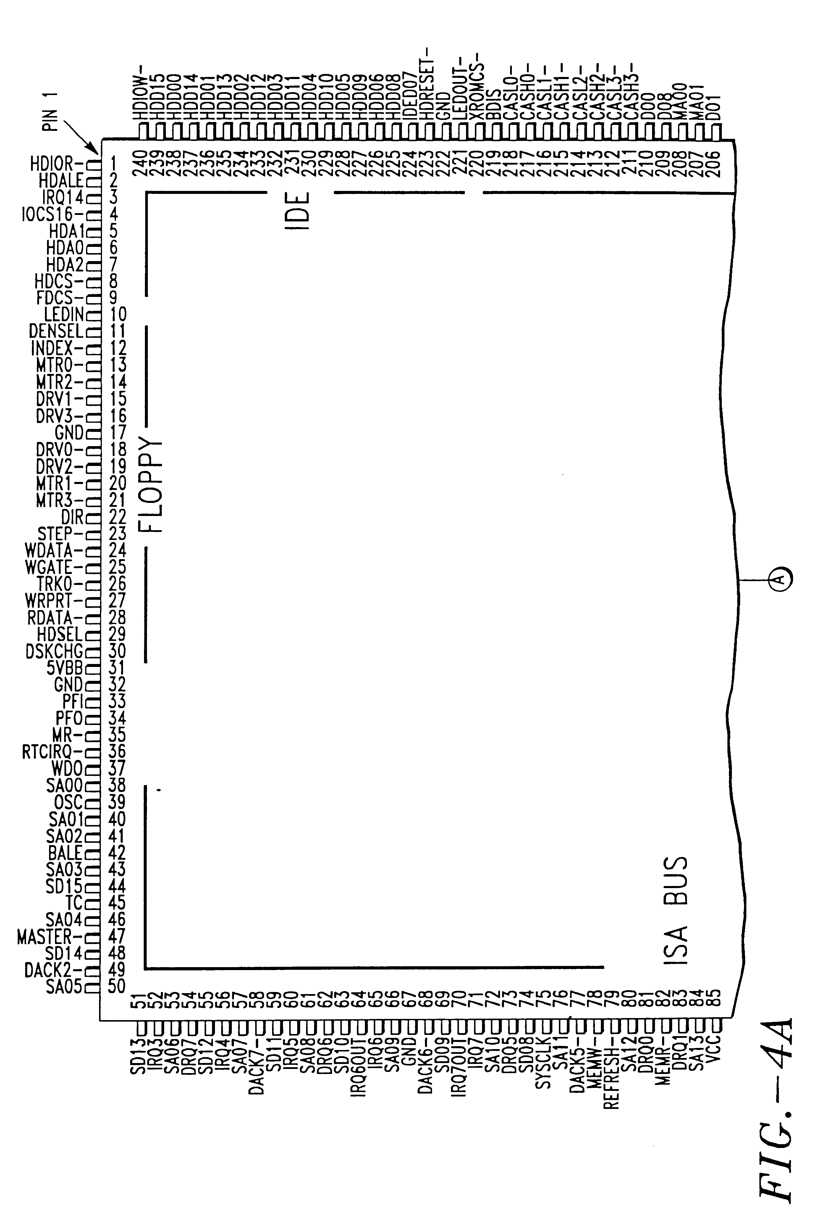
the pin configuration for the expansion bus 24 is given in the table below with corresponding pin numbers for expansion bus connectors A, B, C, D. As mentioned before, bus 24 comprises 94 pins that includes VCC and two GND pins.

The exact pin configuration as illustrated for the expansion bus on FIG. 5 is a critical feature of the invention. Since it forms a single row of pins on the module 10, the pins can be easily connected directly to the expansion bus connectors without having to resort to multiple layer boards to route the PC board tracks from the module 10 to the expansion bus connectors A, B, C, D. Furthermore, as mentioned above, the present invention includes both microprocessor modules as illustrated in FIG. 3, as well as peripheral controller modules such as display controller modules, Ethernet control modules, and PCMCIA compatible modules for extended memory (RAM, ROM, EEPROM, flash memory, etc.), as well as for modem, fax, and network interfaces, and also for wireless ...


PUM


Abstract

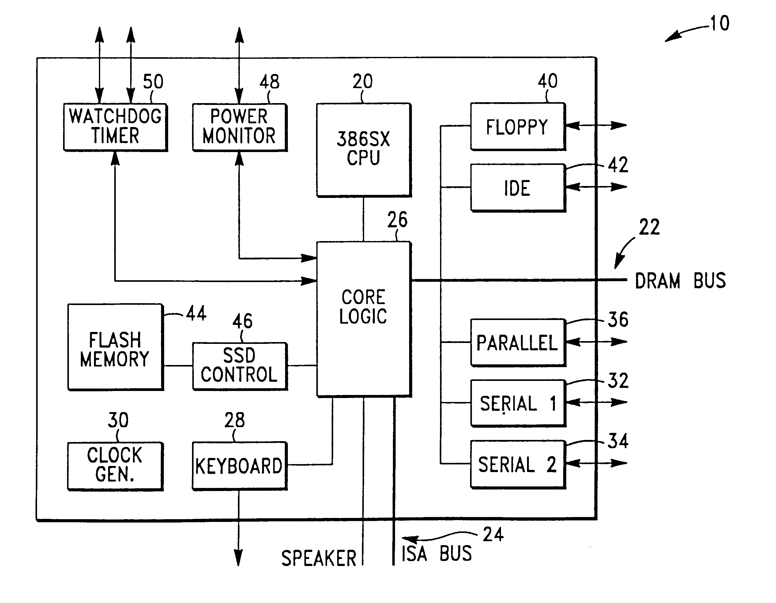
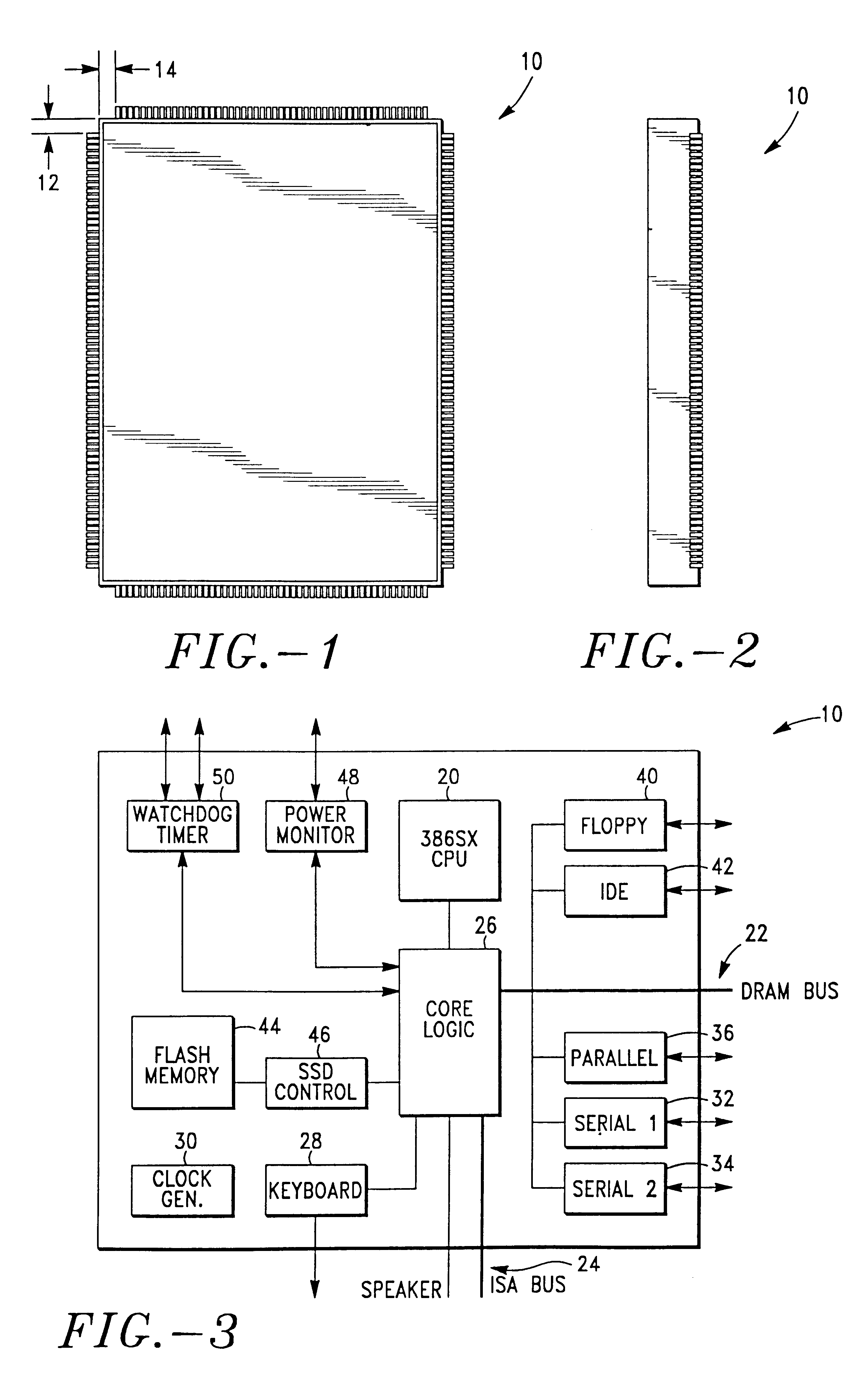
A multi-chip module and a chip set that comprises a plurality of the multi-chip modules. The multi-chip module includes a plurality of functional circuits provided on a substrate, the circuits defining a plurality of signal inputs and outputs. A plurality of pins are secured in a single row along the periphery of the substrate and are connected to the inputs and outputs. The pins include a set of 91 signal pins, two ground pins, and a power pin, the signal pins having a configuration complying in number and signal type with the IEEE-Prequirements to define an ISA bus. The multi-hip module includes a rectangular housing wherein the pins, in the form of gull wing pins, extend laterally from a peripherally extending wall. The ISA bus pins extend along one side and partially along adjacent sides of the rectangular module. The functional circuits of one embodiment of the module include a CPU, serial interfaces, a parallel interface, a hard drive interface, a floppy disk interface, a keyboard interface, and flash memory. Other multi-chip modules can include a PCMCIA interface, an Ethernet interface, or a display controller.

Description

This invention relates to a multi-chip module.The most successful applications of computer technology have been those that people do not see. Microcontrollers and microprocessors govern automotive anti lock braking systems, automatic teller machines, elevators, subway ticket systems, and medical equipment. These hidden computers, otherwise known as embedded systems, permeate our lives. The embedded control market is, in fact, growing significantly faster than the desk top computing market. A major trend is the move from 4- and 8-bit processors to more powerful devices that provide more computing power and enable more "friendly" man-machine interfaces. A study by Desk Top Strategies showed that in 1994 over 320 million 16- and 32-bit embedded control processors were shipped to original equipment manufacturers (OEMs) for use in embedded control applications. In contrast, only 50 million were shipped to desk top computer manufacturers. The compound annual growth rate for 32-bit process...

Claims


Application Information

Patent Timeline
Patent Type & Authority Patents(United States)
IPC IPC(8): G06F15/76G06F15/78
CPCG06F15/7814Y02B60/1225Y02D10/00
Inventor FELDMAN, DAVID L.
Owner ZF MICROSYST
Learn More