Canal hearing device with tubular insert

a hearing device and tubular insert technology, applied in the field of hearing devices, can solve the problems of millions of individuals affected by hearing loss

Inactive Publication Date: 2004-04-20
INSOUND MEDICAL INC
View PDF6 Cites 259 Cited by
  • Summary
  • Abstract
  • Description
  • Claims
  • Application Information

AI Technical Summary

Benefits of technology

The continuous trend for the miniaturization of hearing aids is fueled by the demand for invisible hearing products in order to alleviate the social stigma associating hearing loss with aging and disability. In addition to the cosmetic advantage of canal devices (ITC and CIC devices are collectively referred to herein as canal devices), there are actual acoustic benefits resulting from the deep placement of the device within the ear canal. These benefits include improved high frequency response, less distortion, reduction of feedback and improved telephone use (Chasin, pp. 10-11).
In another embodiment of the invention, the tubular insert comprises only a primary seal system positioned in the bony region while the secondary seal is provided within the main module fitted in the ear canal. Similarly, the main module is appropriately vented to provide a path of least resistance for occlusion sounds while providing additional sealing for the prevention of oscillatory feedback.

Problems solved by technology

Several types of hearing losses affect millions of individuals.

Method used


Image

  • Canal hearing device with tubular insert
  • Canal hearing device with tubular insert
  • Canal hearing device with tubular insert

Examples


experiment a

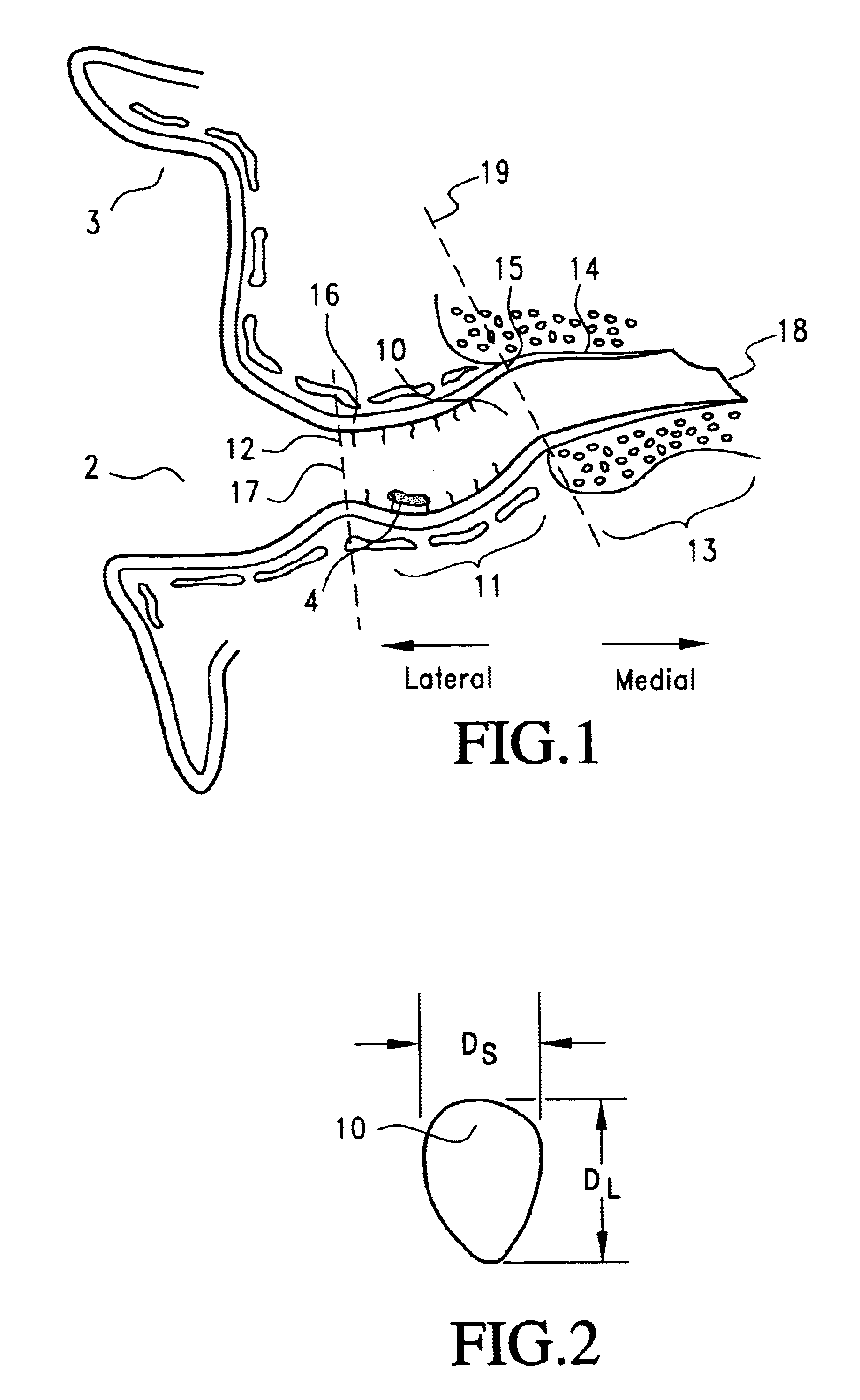
In a study performed by the applicants herein, the cross-sectional dimensions of ear canals were measured from 10 canal impressions obtained from adult cadaver ears. The long (vertical) and short (horizontal) diameters, D.sub.L and D.sub.S respectively, of cross sections at the center of the cartilaginous region 11 and bony region 13 were measured and shown in Table 1 below. The diameters where measured across the widest points of each cadaver impression at each of the two regions. All measurements were taken by a digital caliper (model CD-6"CS manufactured by Mitutoyo). The impression material used was low viscosity Hydrophilic Vinyl Polysiloxane (manufactured by Densply / Caulk) using a dispensing system (model Quixx manufactured by Caulk).

Results and Conclusion

The diameter dimensions of the ear canal vary significantly among adult individuals. In general, variations occur more so across the short diameters (D.sub.S). Although not apparent from the above measurements, the cartilagin...

experiment b

The dual seal concept in relation to acoustic sealing (attenuation) and occlusion effects was simulated in a setup shown in FIG. 20. A test cavity 120, simulating an ear canal and a concha cavity, was produced from a cut section of a syringe. The test cavity 120 had a volume of 1.5 cubic centimeters (cc) with markings indicating the gradual volume within. The test cavity 120 had a lateral opening 121 and a medial opening 123 terminated by a thin diaphragm 123 simulating an eardrum. The test cavity had an ID of approximately 8.5 mm and length of about 27 mm.

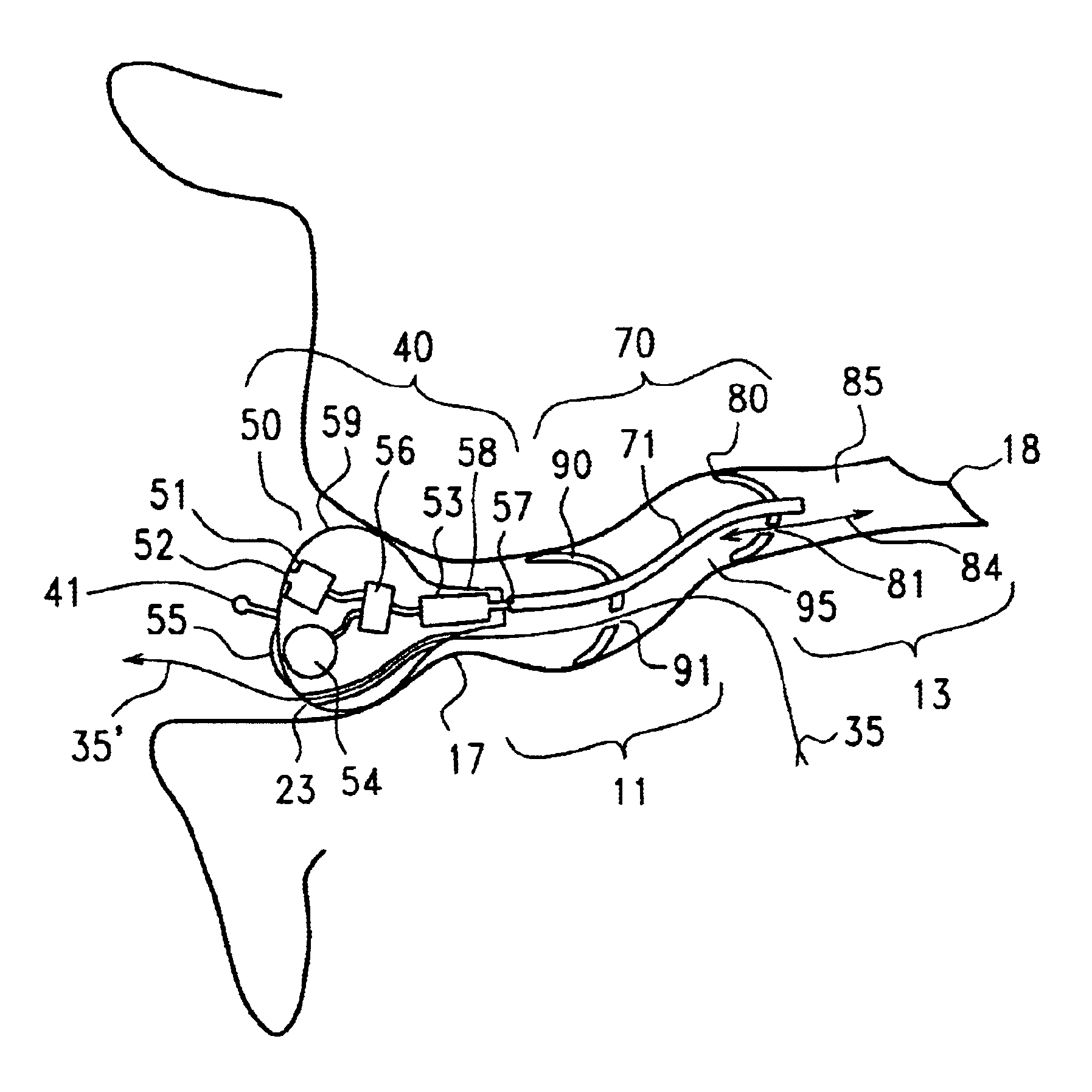
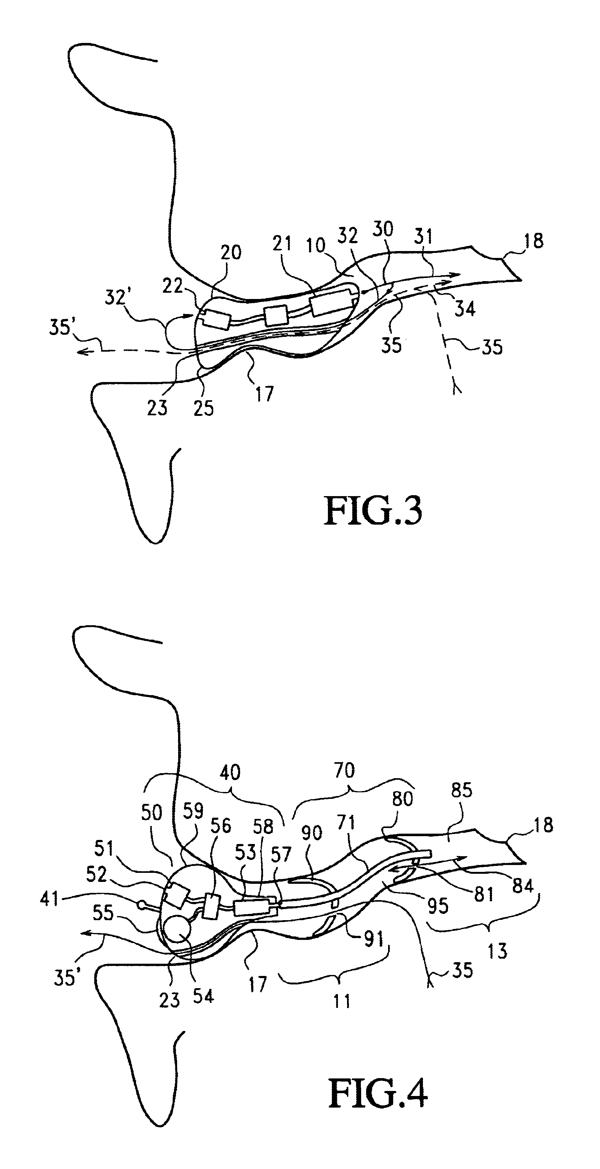
The setup comprised a first receiver R1 (a speaker-model EH-7159 manufactured by Knowles Electronics of Itasca, Ill.) for producing acoustic sounds simulating a receiver 53 (FIGS. 4 and 6) of a hearing aid, and a second receiver R2 (also model EH-7195) for producing sounds simulating occlusion sounds 35 (FIGS. 4 and 6). The receivers R1 and R2 were connected to a signal generator (SG) incorporated within a spectrum analyzer (SA), ...

experiment c

The acoustic conduction advantage, particularly high frequency boosting, of the tubular insert was tested according to the following experiment.

A prototype of the canal hearing device according to the embodiment of FIG. 4 was fabricated. The electroacoustic circuit of FIG. 21 was implemented with a miniature microphone / amplifier M (model FI-3342 manufactured by Knowles Electronics of Itasca, Ill.), class-D receiver R (model FS3379 also manufactured by Knowles Electronics) and miniature 450K Ohm volume trimmer R.sub.G (model PJ-62 manufactured by Microtronics A / S of Denmark). Volume trimmer R.sub.G was connected across the output terminal and the Feedback terminal FB of microphone M. Miniature capacitors C1 and C.sub.2 with values of 0.01 uF and 2.2 uF, respectively were employed. A reed switch assembly (RS) employing a miniature reed-switch (model HSR-003DT, manufactured by Hermetic Switch, Inc. of Chickasha, Okla.) and a miniature Neudymium Iron Boron (NdFeB) magnet (96 in FIG. 18)...


PUM


Abstract

A canal hearing device with a dual acoustic seal system for preventing feedback while minimizing occlusion effects. The two-part device comprises a main module and an elongated tubular insert for conducting sound to the tympanic membrane and sealing within the bony region of the ear canal. The main module is positioned in the cartilaginous portion of the ear canal. The tubular insert comprises a sound conduction tube and a cylindrically hollow primary seal medially positioned in the bony region. The device also comprises a secondary seal laterally positioned in the cartilaginous region. The secondary seal, although providing additional acoustic sealing for the prevention of feedback, is sufficiently vented to provide a path of least acoustic resistance for occlusion sounds within the ear canal. In a preferred embodiment, the tubular insert comprises a coiled skeletal frame to provide high radial flexibility while maintaining sufficient axial rigidity for comfortable, kink-resistant, and consistent placement within the ear canal.

Description

A. Technical FieldThe present invention relates to hearing devices, and, more particularly, to miniature hearing devices that are deeply positioned in the ear canal for improved energy efficiency, sound fidelity, and inconspicuous wear.B. Description of the Prior ArtBrief Description of Ear Canal AnatomyThe external acoustic meatus (ear canal) is generally narrow and tortuous as shown in the coronal view in FIG. 1. The ear canal 10 is approximately 25 mm in length from the canal aperture 17 to the tympanic membrane 18 (eardrum). The lateral (away from the tympanic membrane) part, a cartilaginous region 11, is relatively soft due to the underlying cartilaginous tissue. The cartilaginous region 11 of the ear canal 10 deforms and moves in response to the mandibular (jaw) motions, which occur during talking, yawning, eating, etc. The medial (towards the tympanic membrane) part, a bony region 13 proximal to the tympanic membrane, is rigid due to the underlying bony tissue. The skin 14 in...

Claims


Application Information

Patent Timeline
Patent Type & Authority Patents(United States)
IPC IPC(8): H04R25/00
CPCH04R25/456H04R25/656H04R25/554H04R25/556H04R25/558H04R2225/61H04R2460/11H04R25/658H04R25/603
Inventor SHENNIB, ADNANURSO, RICHARD C.
Owner INSOUND MEDICAL INC
Why Eureka
Try Eureka