Hall-current ion source

a technology of ion source and current, which is applied in the direction of solid cathode, gas-filled discharge tube, ion beam tube, etc., can solve the problems of affecting the operation of ion source, impede the flow of electrons, and poor conductor of anode coating, so as to reduce the effect of operating characteristics, reduce the effect of thermal and/or mechanical effects, and increase the operating time without maintenan

Inactive Publication Date: 2004-06-15
KAUFMAN & ROBINSON
View PDF10 Cites 59 Cited by
  • Summary
  • Abstract
  • Description
  • Claims
  • Application Information

AI Technical Summary

Benefits of technology

In light of the foregoing, it is an overall general object of the invention to provide a Hall-current ion source with improved tolerance to the deposition of a poorly conducting or nonconducting coating on the ion source.
A more specific object of the present invention is to provide a Hall-current ion source in which the deposition of a poorly conducting or nonconducting coating thereon has a reduced effect on operating characteristics.
A further object of the present invention is to provide a Hall-current ion source which has an increased operating time without maintenance when subjected to the deposition of a poorly conducting or nonconducting coating thereon.
Still another object of the present invention is to provide a Hall-current ion source in which an anode coating is minimized though thermal and / or mechanical effects.
In accordance with one specific embodiment of the present invention, a Hall-current ion source of the end-Hall type has an anode that is contoured with one or more recesses in the electron-collecting surface which have areas that are protected from the deposition of externally generated contamination thereon, as well as one or more protrusions that have higher temperatures than the bulk of the anode, thereby increasing the removal or passivation of coatings during operation by the thermal degradation of the coating and the effects of thermomechanical stresses.
In another specific embodiment, which can be combined with the above embodiment, electrically isolated baffle or baffles are located to protect a substantial fraction of the electron-collecting surface of the anode from the deposition of externally generated contamination thereon.

Problems solved by technology

The anode coating may also be a poor conductor rather than a nonconductor, such as would result from a dielectric with poor stoichiometry or the inclusion of impurities.
The formation of a poorly conducting or nonconducting coating on conical surface 28 can impede the flow of electrons to anode 18 and adversely affect the operation of ion source 10.
With increasingly long production runs, however, cleaning is often an undesirable solution.
A poorly conductive or nonconductive coating on an anode is an anode configuration change that can adversely affect performance.
The shape of the ion beam can also be altered, resulting in a reduction of either production rate or useful yield.
If low-voltage operation is desired, it may be difficult or impossible to obtain such operation with a coating on the anode.
Such contractions can also cause arcing damage to the anode.
In either case a direct line-of-sight is not possible from the exterior of the anode to the high-pressure interior through these passages.
Poorly conducting coatings of the type normally deposited on anodes tend to increase conductivity when heated.
This is why operation is often not prevented by an anode coating until after the ion source has been shut down and cooled, after which the poorer conductivity to the cooled anode prevents a subsequent restart.
The ability of the plasma to conduct a discharge current to the anode is limited by the electron density.
Such a reversed sheath results in excessive discharge power loss with much of this loss appearing as anode heating.

Method used


Image

  • Hall-current ion source
  • Hall-current ion source
  • Hall-current ion source

Examples


Embodiment Construction

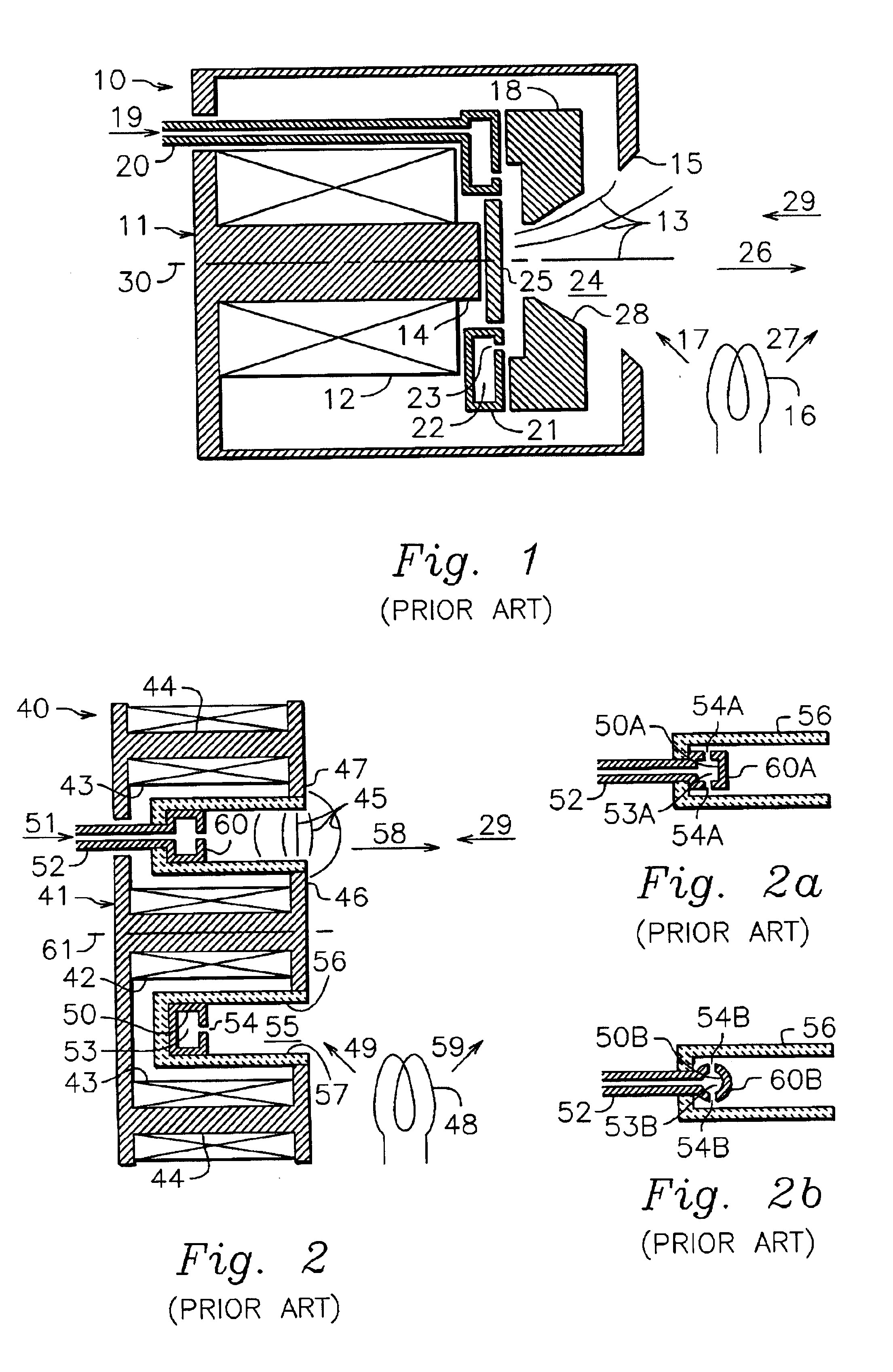
The Mark II end-Hall ion source, originally manufactured by Commonwealth Scientific Corporation and now manufactured by Veeco Instruments Inc., is a prior-art Hall-current ion source with an anode that closely resembles the one shown in FIG. 1. The conical surface of the Mark II anode (corresponding to conical surface 28 in FIG. 1) has an inside diameter of 20 mm and an outside diameter of 36 mm. The Mark II ion source was operated with an argon flow of 100 sccm (standard cubic centimeters per minute). The cathode was the HCES 5000, also first manufactured by Commonwealth Scientific Corporation and later manufactured by Veeco Instruments Inc., was operated with an argon flow of 20 sccm. The sputter target was tantalum and was biased to -500 V relative to the vacuum-chamber ground by a pulsed power supply. An oxygen flow of 50 sccm was directed at the deposition substrate. The experimental configuration of source, target, and deposition substrate was the same as that described by Zhu...


PUM


Abstract

In accordance with one specific embodiment of the present invention, a Hall-current ion source of the end-Hall type has an anode that is contoured with one or more recesses in the electron-collecting surface which have areas that are protected from the deposition of externally generated contamination thereon, as well as one or more protrusions that have higher temperatures than the bulk of the anode, thereby increasing the removal or passivation of coatings during operation by the thermal degradation of the coating and the effects of thermomechanical stresses. In another specific embodiment, which can be combined with the above embodiment, electrically isolated baffle or baffles are located to protect a substantial fraction of the electron-collecting surface of the anode from the deposition of externally generated contamination thereon.

Description

This invention relates generally to ion and plasma sources. More particularly it pertains to plasma and ion sources that utilize a Hall current in the generation of the electric field that accelerates ions in a neutral plasma, and it further pertains to the performance of such sources and their being able to operate in adverse environments in which poorly conducting or nonconducting coatings are formed or deposited upon the ion sources or particular components thereof.This invention can find application in industrial processes such as sputter etching, sputter deposition, coating and property enhancement. It can also find application in electric space propulsion.The acceleration of ions to form energetic beams of ions has been accomplished both electrostatically and electromagnetically. The present invention pertains to sources that utilize electromagnetic acceleration. Such sources have variously been called plasma, electromagnetic, and gridless ion sources. Because the ion beams ar...

Claims


Application Information

Patent Timeline
Patent Type & Authority Patents(United States)
IPC IPC(8): H01J27/24H01J27/02
CPCH01J27/146
Inventor KAUFMAN, HAROLD R.KAHN, JAMES R.ROBINSON, RAYMOND S.ZHURIN, VIACHESLAV V.
Owner KAUFMAN & ROBINSON
Why Eureka
Try Eureka