
Omnidirectional microscale impact switch

a micro-scale impact switch and micro-scale technology, applied in the direction of speed/acceleration/shock measurement, contacts, instruments, etc., can solve the problems of large volume demands, too large switch configuration, too large, etc., and achieve the effect of reducing the number of insertions

Inactive Publication Date: 2004-07-20
UNITED STATES OF AMERICA THE AS REPRESENTED BY THE SEC OF THE ARMY
View PDF5 Cites 48 Cited by
  • Summary
  • Abstract
  • Description
  • Claims
  • Application Information

AI Technical Summary

Benefits of technology

The present invention meets the need for an extremely miniature, very low cost, fast-acting, unpowered, omnidirectional impact switch. In particular, there is a need in the munitions fuzing area for an ultra-miniature, inexpensive, omnidirectional, fast-acting impact-switch, also known as a "g-switch", that can be integrated with a fuze circuit. The need for small size comes from the increasing miniaturization required to pack more functionality into small caliber weapons, e.g., a 20 -mm bursting-round fuze, which also must contain sophisticated timing, sensing or targeting electronics and whose payload must be maximized for effect. This puts space inside the projectile at a premium.
The invention allows for efficient methods of electrical connection to, and integration with, a circuit. For example, in a fuze application, the invention can be integrated directly with the fuze controller circuit via surface-mount techniques on a hybrid circuit board, or it can be flip-chip integrated directly with fuze ASIC chips, and may in time be possible to integrate on the same substrate with or as part of an ASIC or microcontroller chip itself.
The invention allows for low cost of manufacture by using technology related to the semiconductor wafer and silicon chip manufacturing industry. By virtue of wafer-to-wafer bonding techniques in a semiconductor foundry clean-room environment, and subsequent dicing, the following advantages are obtained:
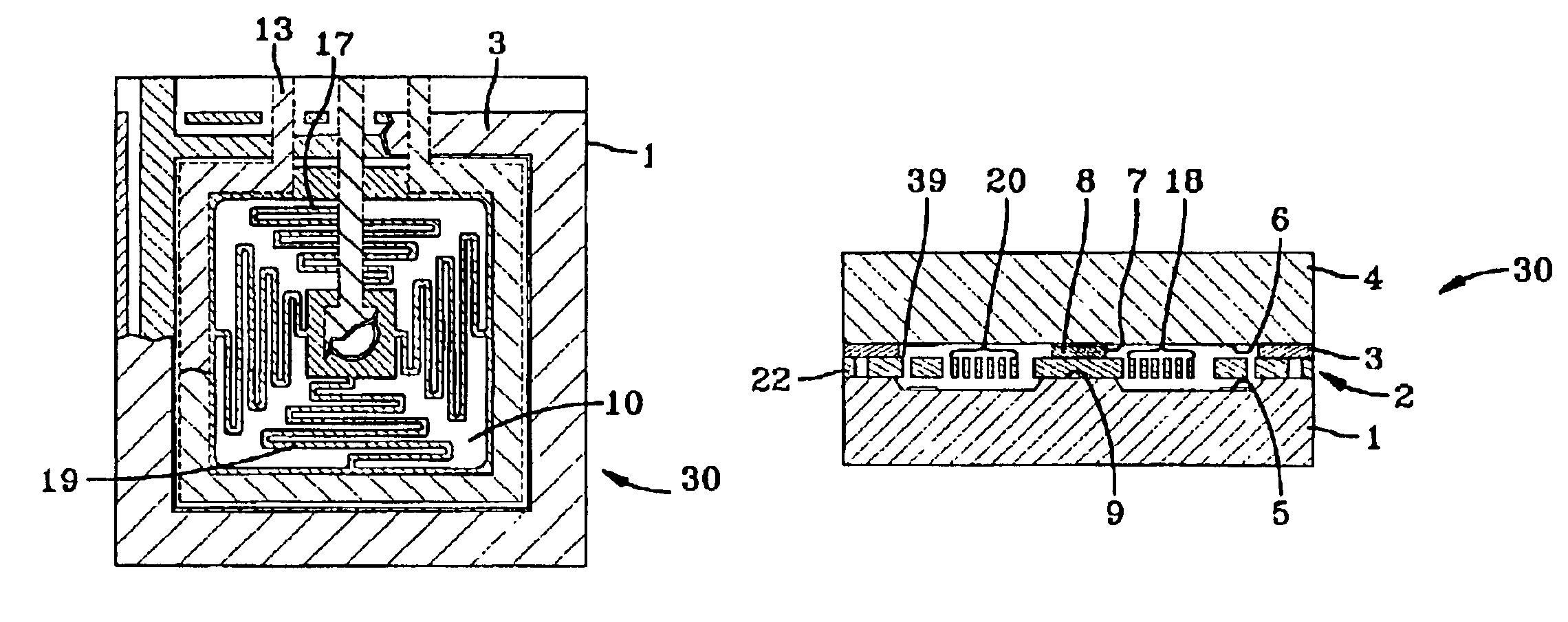
The invention may be extremely small (about 1 cubic mm), integratable with electronics, surface-mountable, rugged, cheap and fast-acting. The invention does not draw power, has a large dynamic range, has different sensitivity in different axes, and can be ganged with identical sensors or an array of sensors with different thresholds on the same substrate. The invention offers a number of improvements over the prior art:
Its actuation mechanism does not require "tilting" of a cylindrical mass, with the associated moments of inertia, hence, it can act faster.
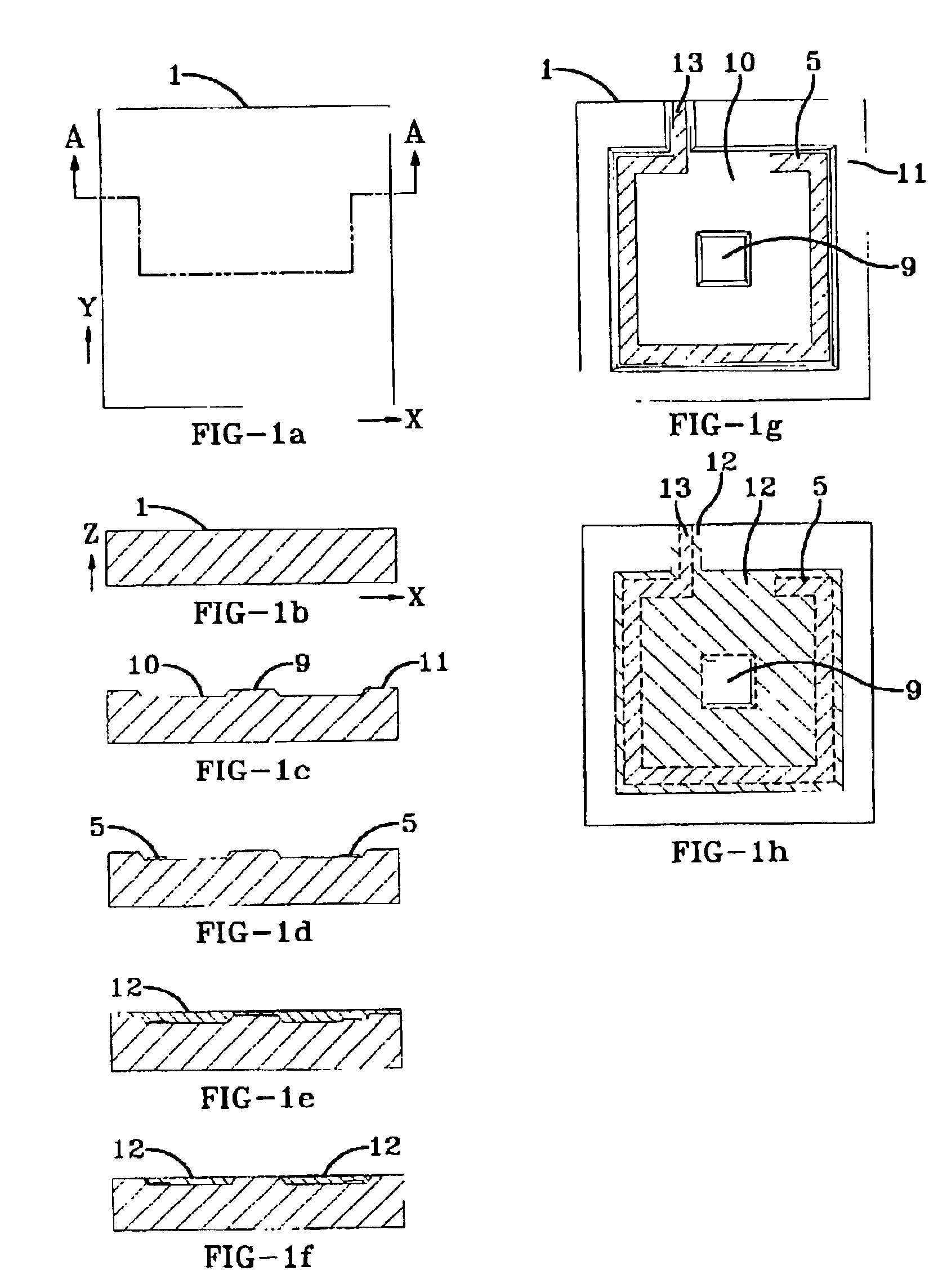
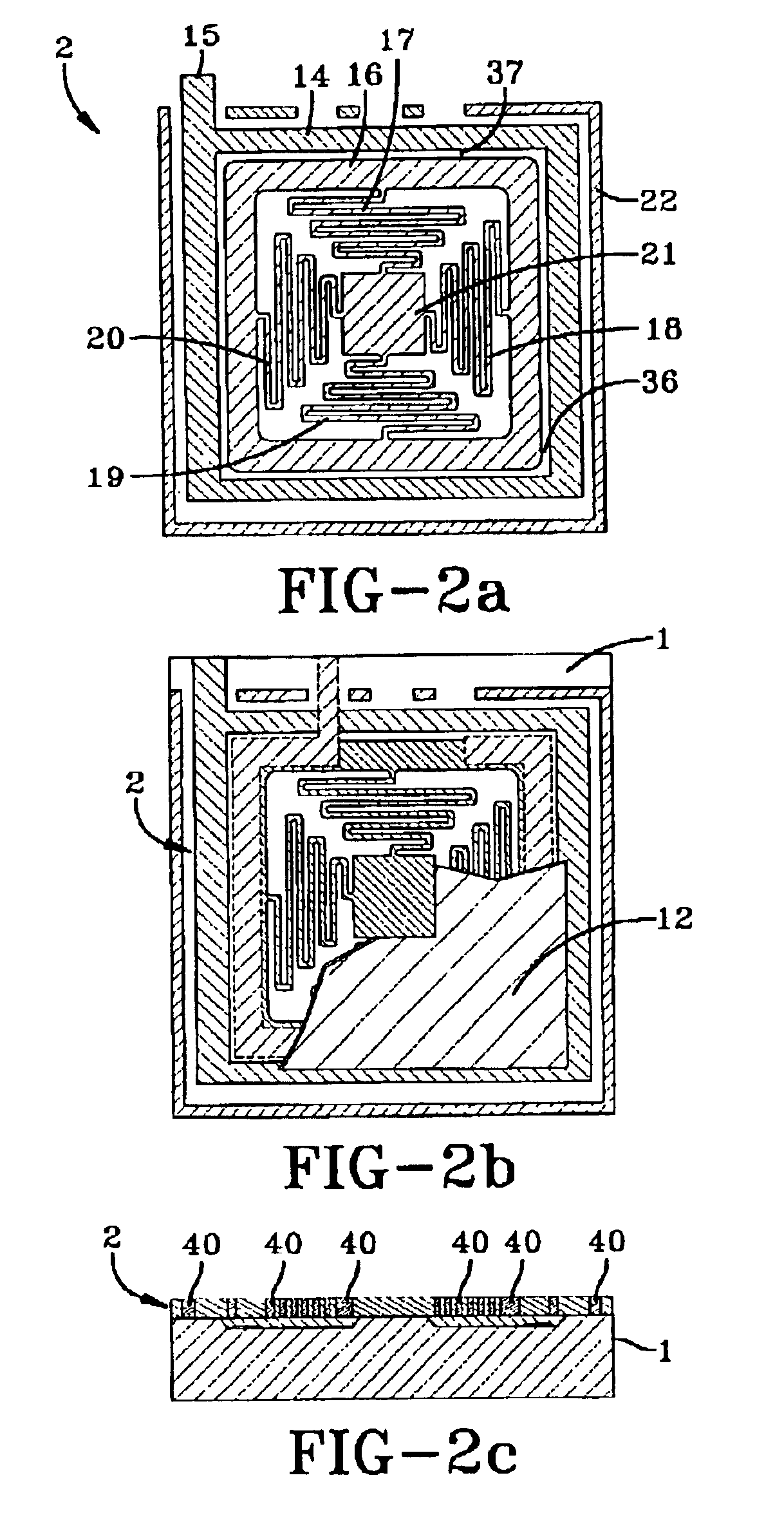
The configuration of a center-supported spring / mass assembly optimizes the size of proof mass relative to overall device footprint and also makes it easy to run contact leads around the outside of the mass and simplifies fabrication (no need to deposit tracks and then insulate them from the mass).

Problems solved by technology

Some prior art devices are described in U.S. Pat. Nos. 6,314,887; 4,916,266; 4,789,762; 4,174,666; and 3,899,649; However, these switches suffer from many disadvantages in the munition fuzing application and in many other applications, as will be delineated.
A problem exists in the munition fuzing industry because the need for "smarter" weapons often requires additional space within the weapon for signal and guidance electronics, power management, and sensors, while the need for greater lethality or payload makes simultaneous demands on volume.
Another aspect of the problem is that with current trends, the domestic precision small-parts manufacturing industry is diminishing or moving overseas, so that an alternative and economical domestic source is needed for future fuze components production.
The prior art impact-switch implementations, in general, involve switch configurations that are too bulky, too slow-acting, are imprecise, are too expensive to manufacture, or are difficult or unsuitable to integrate with current surface-mount (hybrid circuit) or multi-chip-module-based fuze circuit implementations.
Also, current day threshold switches used in fuzing typically involve glass-metal seals or polymeric materials that naturally degrade with time and changing conditions.
Are too large for, or do not offer means for, direct integration in multi-chip-modules, surface mount circuits, or even micro-controller chips;
Are expensive, due to reasons that follow;

Method used


Image

  • Omnidirectional microscale impact switch
  • Omnidirectional microscale impact switch
  • Omnidirectional microscale impact switch

Examples


Embodiment Construction

Other embodiments of the present invention can be envisioned that use a different pattern for the suspension springs, or a different shape of the proof mass, for example a varying thickness in the square proof mass, or perhaps a circular proof mass with a circular contact electrode, etc., but these are the same invention. A setback-hardened design would reduce or eliminate gap 38 and bottom contact electrode 5. With developments in the industry it will be possible to form most or all of the features of device layers 2 and 200 in the aforementioned embodiments by advanced molding or hot-embossing mold transfer processes instead of a direct micromachining technique. For example, the micromachining operation can be used to create a master mold that is then used to "print" molds for the electroplating of the product devices.

While the invention has been described with reference to certain preferred embodiments, numerous changes, alterations and modifications to the described embodiments ...


PUM


Abstract

The invention is a normally-open, momentary, non-latching, inertial thresholding switch 30, fabricated on a substrate 1 in a planar configuration, using no cylindrical tilt mass, with low mass 16 and small switch gap 36, 37, 38, 39 to allow fast switch action and rapid reset. Of ultra-miniature, rugged construction, its high mechanical frequency limits sensitivity to vibration inputs.

Description

FEDERAL RESEARCH STATEMENT[The inventions described herein may be manufactured, used and licensed by or for the U.S. Government for U.S. Government purposes.]The invention relates in general to inertial switches and in particular to very small electro-mechanical inertial switches.To assure safety in the transportation, handling, and deployment of gun-fired and other explosive munitions, munition-fuze safety standards require that two unique and independent aspects of the launch environment must be detected in the weapon fuze system before the weapon can be enabled to arm. Examples of the aspects of the launch environment that are sensed electronically or mechanically are: setback acceleration, spin, tube exit, and airflow. Munition fuzes also perform targeting functions, which can include electromagnetic target detection, range estimation, target impact detection, or grazing impact detection.Many of the above sensing functions can be performed either electronically or mechanically, ...

Claims


Application Information

Patent Timeline
IPC IPC(8): H01H35/14H01H1/00
CPCH01H35/14H01H1/0036
Inventor ROBINSON, CHARLES H.
Owner UNITED STATES OF AMERICA THE AS REPRESENTED BY THE SEC OF THE ARMY
Learn More