Electrostatic deposition of particles generated from rapid expansion of supercritical fluid solutions

a supercritical fluid and electrostatic deposition technology, applied in the direction of liquid solution solvent extraction, solvent extraction, separation process, etc., can solve the problems of insufficient film thickness and uniformity control, difficult or impossible deposition of particles in the range of 10-500 nm on the surface, and high cos

Inactive Publication Date: 2004-08-24
BATTELLE MEMORIAL INST
View PDF25 Cites 55 Cited by
  • Summary
  • Abstract
  • Description
  • Claims
  • Application Information

AI Technical Summary

Problems solved by technology

A long-standing difficulty with the RESS process is that particles in the range from 10-500 nm are difficult or impossible to deposit on a surface since their extremely low mass causes them to remain entrained in the expansion gas.
Liquid spraying is not a true thin film technique since relatively large particles or agglomerations of molecules actually impact the substrate surface.
Most conventional methods use environmentally problematic volatile organic solvents, do not offer sufficient film thickness and uniformity control, and / or are costly.

Method used


Image

  • Electrostatic deposition of particles generated from rapid expansion of supercritical fluid solutions
  • Electrostatic deposition of particles generated from rapid expansion of supercritical fluid solutions
  • Electrostatic deposition of particles generated from rapid expansion of supercritical fluid solutions

Examples


example 1

Supercritical carbon dioxide solutions of three different fluoropolymer were used to generate different types of coatings on assorted substrates. The first was a copolymer of tetrafluoroethylene / hexafluoropropylene (19.3%) (TFE / HFP) whose solubility in CO.sub.2 has been previously reported by Tuminello et al., Dissolving Perfluoropolymers in Supercritical Carbon Dioxide, Macromolecules 1995, 28, 1506-1510 and Rindfleisch et al., Solubility of Polymers and Copolymers in Supercritical CO.sub.2, J. Phys. Chem. 1996, 100, 15581-15587. The second was a copolymer of tetrafluoroethylene / hexafluoropropylene / vinylidene fluoride (THV 220A) that was used as received from Dyneon LLC, 6744 33.sup.rd Street North, Oakdale, Minn. 55128. This polymer has a reported melting point of 120.degree. C. The third polymeric material, poly(1,1-dihydroperfluorooctylacrylate) or PFOA, was synthesized using methods described in DeSimone et al., Science 1992, 257, 945-947. Each of these materials was dissolved ...

example 2

A fluorescent organic compound, coumarin 153, was mixed into the supercritical fluid solution with the THV polymer at a dye-to-polymer mass ratio of 1:20 at the conditions described above. These materials by themselves do not form a solid solution. A uniform particle matrix coating was again generated but in this case the coating had a distinct yellow hue characteristic of the dye. Under a high-power fluorescence microscope the coating was strongly fluorescent although individual dye particles cannot be resolved. A rapid photo-bleaching (approximately 5 sec half life) of the coating was visually observed, possibly because of the finely divided nature of the dye particles.

example 3

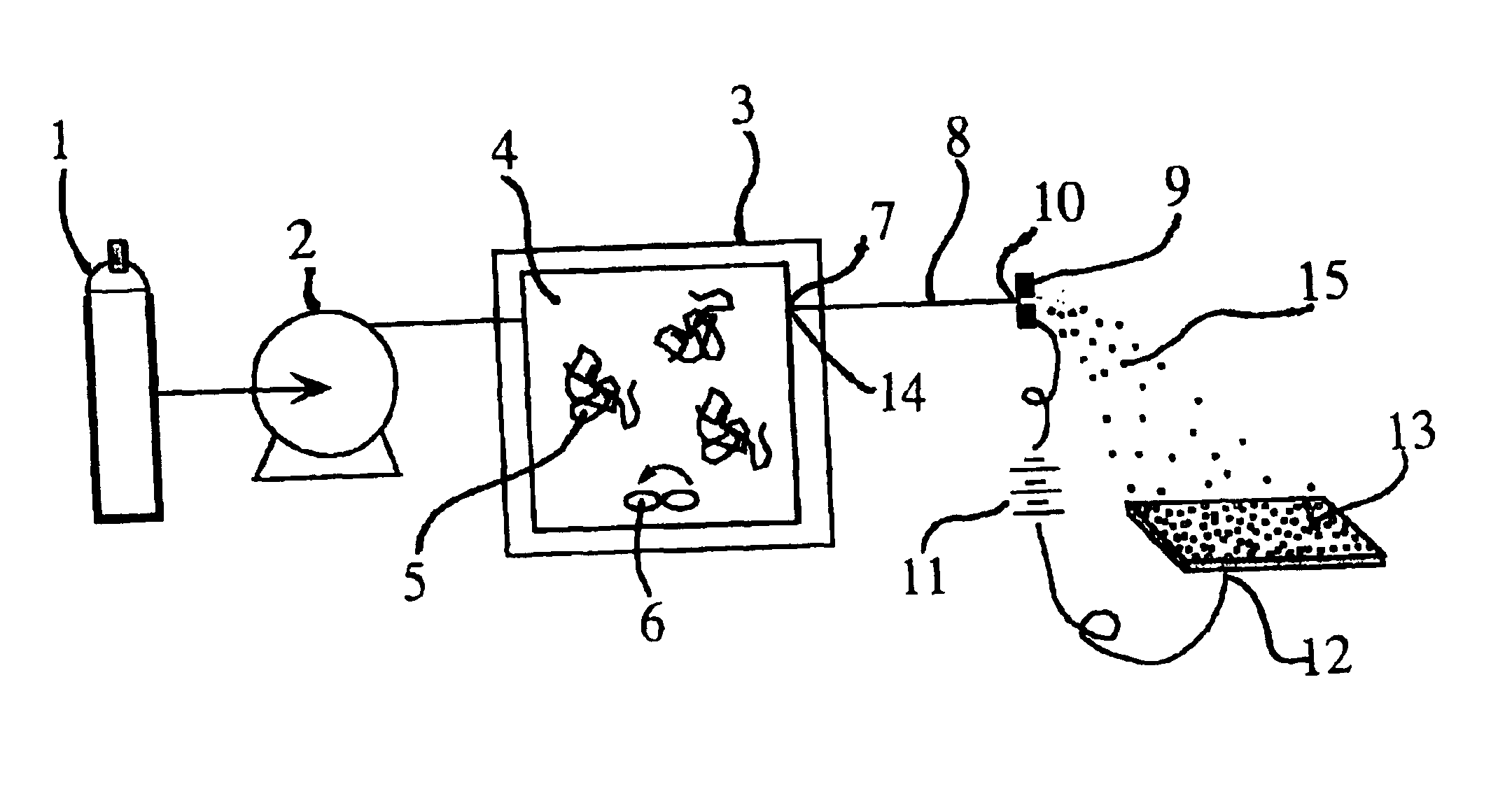
The RESS process for the TFE / HFP polymer was adjusted to produce a mixture of ultra-fine fibers and particles. In this case, the pressure of the supercritical solution in the pressurized vessel 3 upstream of the capillary restrictor nozzle 8 was just slightly above the cloud point pressure. Under these conditions a phase separation occurs within the capillary restrictor nozzle 8 generating a polymer-rich liquid phase that wets the wall of the capillary. Upon exiting the capillary tip, this viscous liquid phase is drawn into ultra-small fibers. Since the screen is positioned away from the high-velocity RESS jet, the fiber migration to this substrate is primarily driven by the electrostatic forces as is the case for the ultra-small particles.


PUM

PropertyMeasurementUnit
mean particle sizeaaaaaaaaaa
thicknessaaaaaaaaaa

Abstract

A method for depositing a substance on a substrate that involves forming a supercritical fluid solution of at least one supercritical fluid solvent and at least one solute, discharging the supercritical fluid solution through an orifice under conditions sufficient to form solid particles of the solute that are substantially free of the supercritical fluid solvent, and electrostatically depositing the solid solute particles onto the substrate. The solid solute particles may be charged to a first electric potential and then deposited onto the substrate to form a film. The solute particles may have a mean particle size of less than 1 micron.

Description

FIELDThis application relates to methods for electrostatically depositing a substance on a substrate.The rapid expansion of supercritical fluid solutions through a small orifice (referred to herein as the "RESS" process) produces an abrupt decrease in dissolving capacity of the solvent as it is transferred from a supercritical fluid state, having near liquid density, to a very low density phase after the expansion. This abrupt transition in solvent characteristics results in the nucleation and growth of nanometer-sized particles from any low vapor pressure solute species that are dissolved in the solution prior to expansion. Because the solvent is transformed into the gas phase during the RESS expansion, RESS products are generated "dry" since they are substantially free of residual solvent. A long-standing difficulty with the RESS process is that particles in the range from 10-500 nm are difficult or impossible to deposit on a surface since their extremely low mass causes them to r...

Claims


Application Information

Patent Timeline
Patent Type & Authority Patents(United States)
IPC IPC(8): B05D1/04B05D1/02
CPCB05D1/025B05D1/04
Inventor FULTON, JOHN L.DEVERMAN, GEORGE
Owner BATTELLE MEMORIAL INST
Why Eureka
Try Eureka