
Method and apparatus for wet type flue-gas desulfurization

a technology of wet type flue gas and desulfurization method, which is applied in lighting and heating apparatus, machine/engine, separation process, etc., can solve the problems of short stirring liquid stream, decreased stirring efficiency, and uneven distribution of air bubbles, so as to reduce the number of nozzles and reduce the power of the pump. , the effect of large oxidation ability

Inactive Publication Date: 2004-09-07
MITSUBISHI HITACHIPOWER SYST LTD
View PDF10 Cites 1 Cited by
  • Summary
  • Abstract
  • Description
  • Claims
  • Application Information

AI Technical Summary

Benefits of technology

Therefore, an object of the present invention is to provide a wet type exhaust gas desulfurization apparatus and a wet type flue gas desulfurization method in which the contact area between liquid and air can be increased largely.
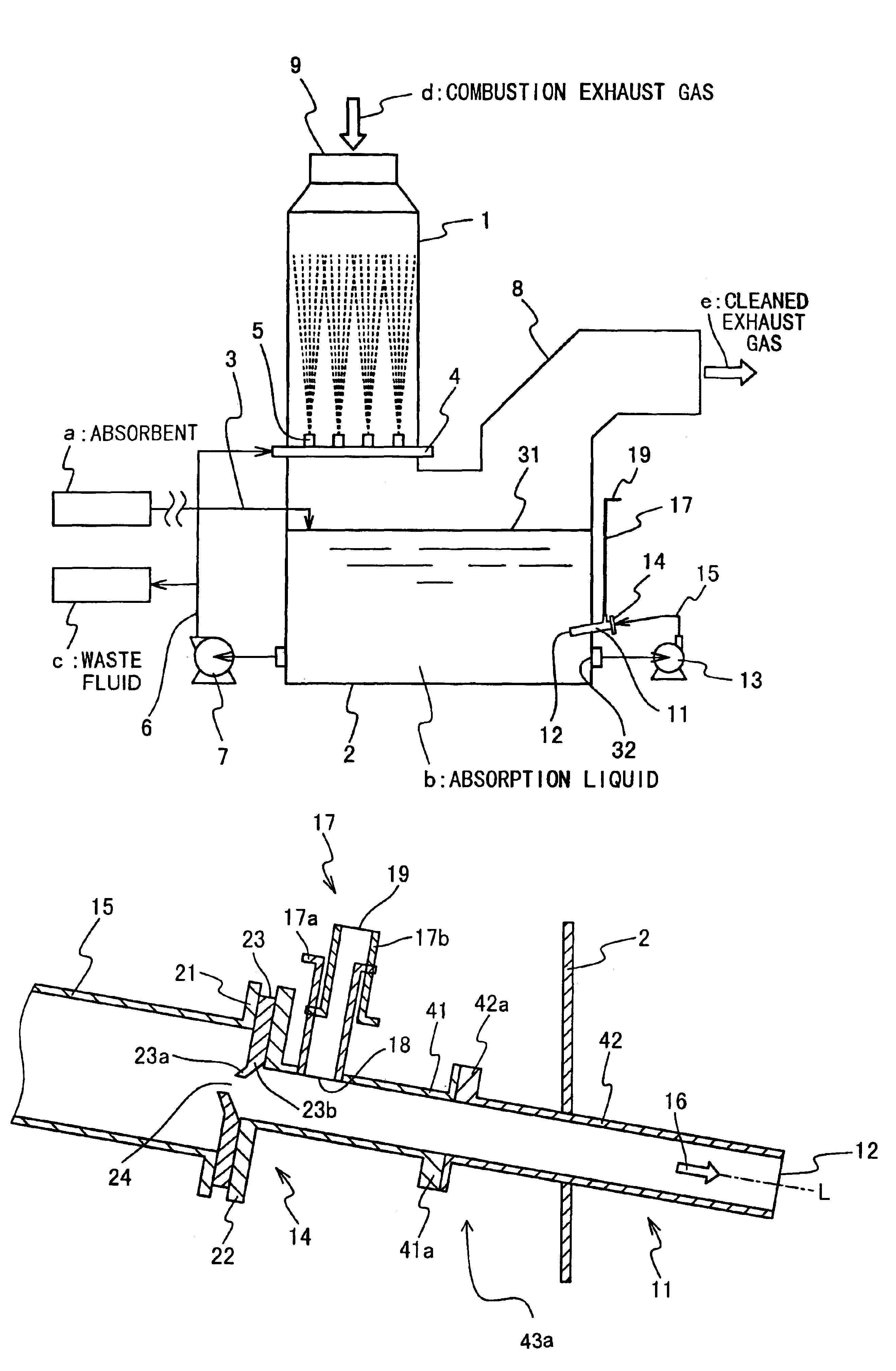
The minute air bubbles distributed in the wide region in this way contact the absorption liquid with a large area and can oxidize sulfite in the absorption liquid efficiency. Because a single nozzle has the sufficiently large oxidation ability, it is possible to reduce the number of nozzles, which become troublesome in the check cleaning work. Because the large flow is generated, the discharging position of the mixture stream of air and liquid can be freely set. Because the pump 13 does not catch air bubbles, the power of the pump can be reduced. The increase of the flow by the occurrence of the wake promotes a stirring effect. The air supply blower is not always necessary. The oxidation in a high efficiency, especially perfect oxidation can be realized without any blower, as described later.

Problems solved by technology

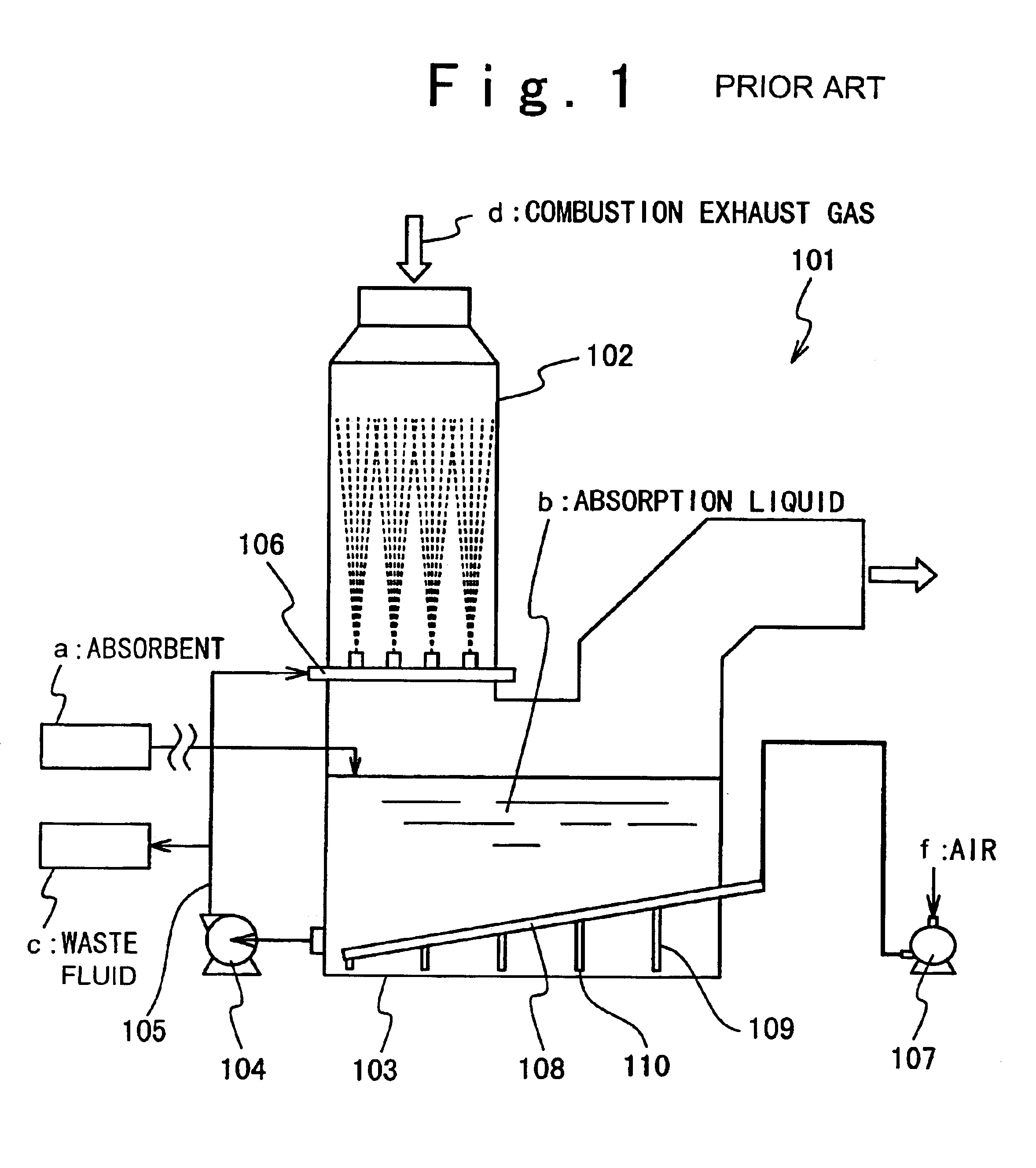
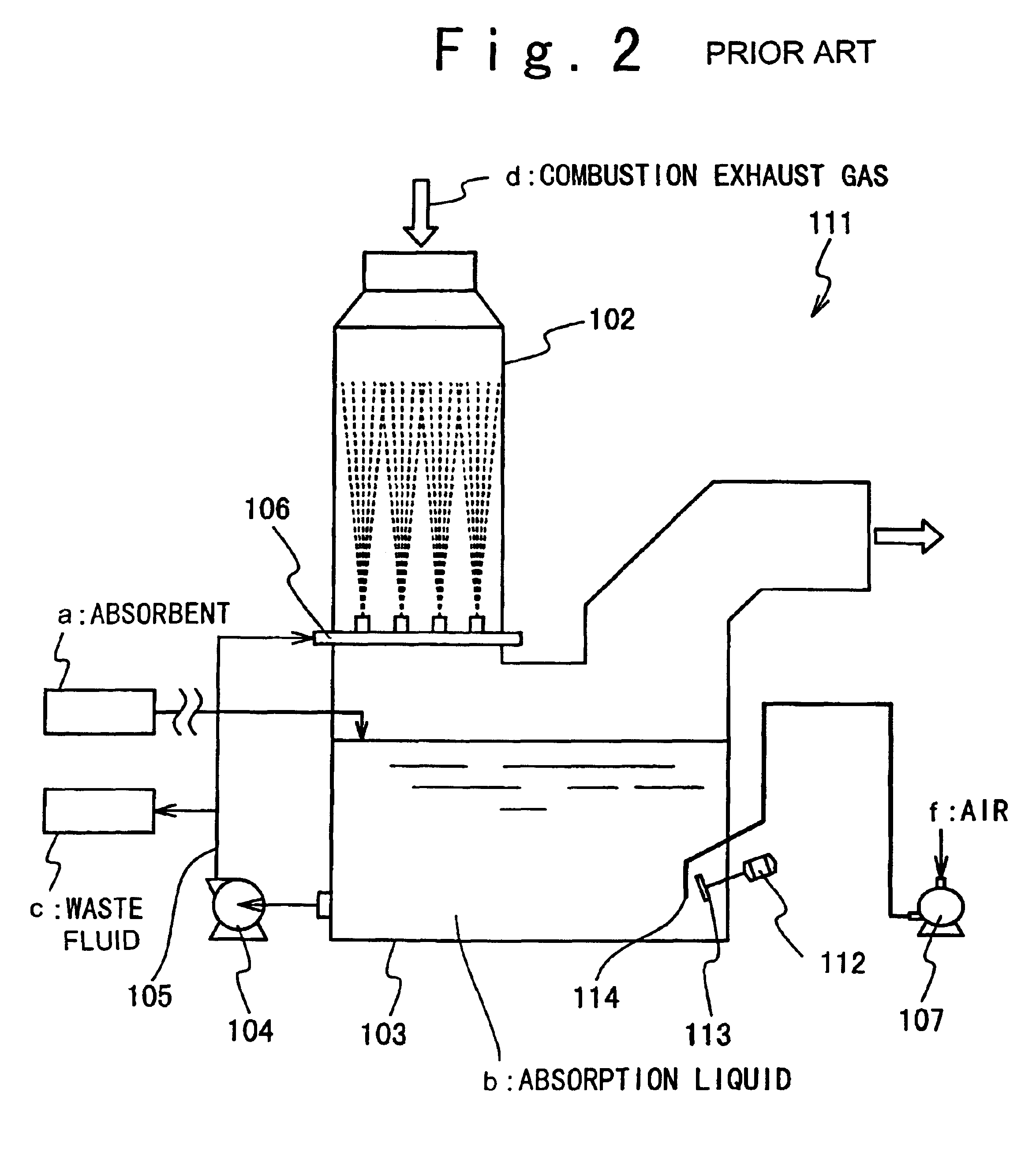
As a result, the outreach of the stirred liquid stream becomes short and the stirring efficiency decreases.
Even if the mixture stream of the air and the liquid is spouted from the jet nozzle 117 or discharge pipe 122 in such a condition, the air bubbles are not uniformly distributed and the perfect oxidation is difficult.

Method used


Image

  • Method and apparatus for wet type flue-gas desulfurization
  • Method and apparatus for wet type flue-gas desulfurization
  • Method and apparatus for wet type flue-gas desulfurization

Examples


Embodiment Construction

The specification of a demonstration apparatus is as follows:

(1) The cross section of the absorption tower 1 was 4 square meters and the effective height of the absorption tower 1 was 12 m to the spray pipe 4.

(2) The cross section of the liquid reservoir 2 was 2 m.times.4 m and the relative height from the bottom to the spray pipe 4 was 3.5 m.

(3) The two spray pipes 4 are provided and the nominal diameter is 150 A. Four absorption liquid discharge ports 5 with the nominal diameter of 40 A and the length of 100 mm were provided to direct an upward direction.

(4) The nominal diameter of the pipe 15 was 150 A.

(5) The nominal diameter of the nozzle 11 was 100 A and the hole diameter of the reduction section hole 24 was 75 mm. The discharging port 12 was set to the height position of 0.5 m from the floor (bottom) surface in the horizontal position of 0.4 m from the side wall (the side walls oppose to each other in the distance of 2 m). An obliquity angle of the centerline L of the flow pa...


PUM

PropertyMeasurementUnit
heightaaaaaaaaaa
relative heightaaaaaaaaaa
lengthaaaaaaaaaa

Abstract

A wet type exhaust gas desulfurization apparatus includes a liquid reservoir which reserves absorption liquid containing absorbent and sulfite, a desulfurizing system which removes sulphur dioxide from combustion exhaust gas and forms sulfite, and an air supplying and circulating device which has a reduction section and supplies air to said liquid reservoir using a negative pressure generated due to said reduction section to oxidize the sulfite.

Description

The present invention relates to a wet type exhaust gas desulfurization apparatus and method.Conventionally, in spaces for production and residence such as a plant and a building, an incinerator like a boiler is used. Such an incinerator burns fuel. In this time, if being contained in the fuel, the sulfur component is exhausted as sulphur dioxide (SO.sub.2) gas without being fixed in ash. The sulphur dioxide gas is showered on the ground as acid rain and affects a human body, an animal, and natural environment. Generally, the incinerator is provided with an exhaust gas desulfurization apparatus not to affect adverse influence.Most of the exhaust gas desulfurization apparatuses installed in the large-sized combustion facilities are a wet type. In the wet type exhaust gas desulfurization apparatus, the exhaust gas is made to contact alkaline absorption liquid like limewater and the sulphur dioxide gas is changed into sulfite. In this way, the sulfite is absorbed in the absorption liqu...

Claims


Application Information

Patent Timeline
Patent Type & Authority Patents(United States)
IPC IPC(8): B01D53/50B01D53/14F23J15/04B01D53/34B01D53/77B05B7/04
CPCB01D53/1481B01D53/504Y02A50/20
Inventor ONIZUKA, MASAKAZUTAKASHINA, TORU
Owner MITSUBISHI HITACHIPOWER SYST LTD
Learn More