Scanning laser ophthalmoscope optimized for selective retinal microphotocoagulation

a laser ophthalmoscope and selective technology, applied in the field of scanning laser ophthalmoscopes, can solve the problems of difficult interpretation of psychophysical testing and treatment precision, novel approach however not ideal, and the inability to image directly the impact of such therapeutic laser sources with a traditional co-pupillary scanning laser ophthalmoscope, so as to simplify the angulation of external laser beams

Inactive Publication Date: 2004-09-14
JOZEF F VAN DE VELDE
View PDF2 Cites 111 Cited by
  • Summary
  • Abstract
  • Description
  • Claims
  • Application Information

AI Technical Summary

Problems solved by technology

The use of different instruments renders the comparison of images, the interpretation of psychophysical testing and precision of treatment more difficult.
This novel approach however is not ideal because of the technical difficulties in implementing safety controls for such a scanning therapeutic laser beam, the difficulty in modulating the scanning laser beam over a range from non-coagulating to coagulating energies at video bandwidths, and the non-thermal complications of high intensity pulsed laser beams in the nanosecond domain with an inappropriate duty cycle.
However, it is impossible to image directly the impact of such therapeutic laser source with a traditional co-pupillary scanning laser ophthalmoscope.
This optical arrangement makes the art of precise focussing of a small therapeutic laser beam on specific retinal levels, especially a Gaussian beam more difficult in the presence of wavefront aberrations or large diameter entrance beams.
More specifically, focussing with a contactglass on the retina is subject to eye and head movements of the patient that easily brings the Gaussian beam out of focus because of its high divergence.
However, photocoagulating ophthalmoscopes have been limited when consistent small or localized laser applications in the retina are desired because the anatomical changes caused by the therapeutic laser are difficult if not impossible to visualize during treatment in the presence of photocoagulating light.
The surgeon, upon recognizing the minimal anatomical changes on the retina, is also handicapped by a substantial human reaction time delay before he can interrupt the therapeutic laser.
During this delay the laser continues to deliver energy to the retina and changes in the subject's fixation may occur.
Since the reaction time of the surgeon may exceed 200 ms, a 100 ms laser application can easily be wrongly targeted on the retina in the case of misalignment.
Also, it is difficult to permanently document previous applications on the retinal image because threshold applications themselves are usually not visible some time after the initial treatment.

Method used


Image

  • Scanning laser ophthalmoscope optimized for selective retinal microphotocoagulation
  • Scanning laser ophthalmoscope optimized for selective retinal microphotocoagulation
  • Scanning laser ophthalmoscope optimized for selective retinal microphotocoagulation

Examples


Embodiment Construction

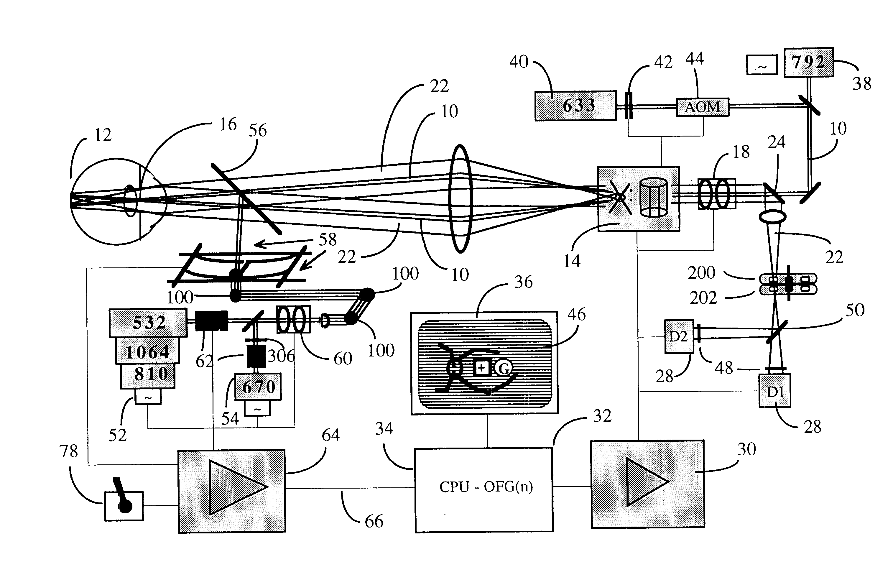
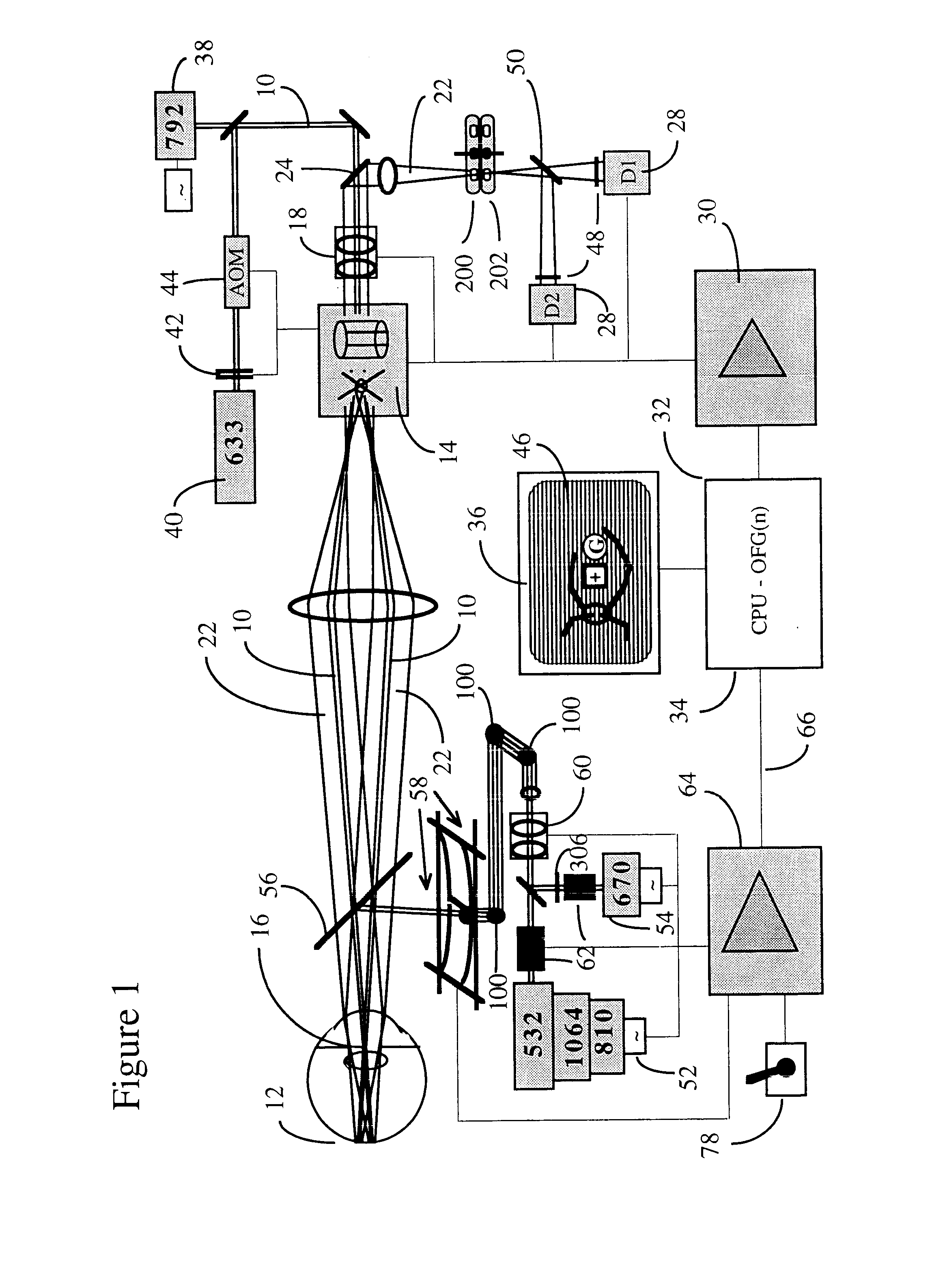
A typical embodiment of the confocal scanning laser ophthalmoscope for retinal microphotocoagulation is illustrated in FIG. 1. The principles of scanning laser ophthalmoscopy are described in detail in the prior art (Pomerantzeff, Saban, Webb, Plesch). Features of the confocal scanning laser ophthalmoscope that are relevant to the invention are further discussed.

I. The Confocal Scanning Laser Retinoscope

A prefocussed Gaussian beam of laser light 10, e.g. consisting of a merger of polarized He--Ne 633 nm and diode 792 nm, and having an approximate diameter of 1.0 mm at the entrance of the eye, is further focussed by the eye optics of approximately 60 D power, to a spot, typically between 10 and 30.mu. in diameter at a retinal plane, and this spot is scanned over the posterior pole of the eye 12 in a sawtooth manner with the help of scanning optics, currently comprising a polygon and galvanometer driven mirror 14. Fast horizontal 15 KHz and slower vertical 60 Hz deflections of this fl...


PUM


Abstract

A combination of a confocal scanning laser ophthalmoscope and external laser sources is used for microphotocoagulation purposes. An opto-mechanical linkage device and beamsplitter is used to align the pivot point of the Maxwellian view of the scanning laser ophthalmoscope with the pivot point of non-scanning external laser beams. The same pivot point is necessary to minimize wavefront aberrations and to enable precise focussing of a therapeutic laser beam on the retina. An AOM and / or two-dimensional AOD can be inserted in the pathway of the Gaussian therapeutic beam to control intensity and spatial pattern of small and short-duration pulses. The location of the external laser beam on the retina is determined with the help of two synchronized detectors and image processing. One detector is used to localize moving fiducial landmarks of the retina. A second detector is used to locate on the retina the external laser aiming beam. Two different confocal apertures are used. Polarizing the aiming beam is necessary to further reduce unwanted reflections from the anterior corneal surface.

Description

1. Field of InventionThe invention relates generally to instruments for examining and treating the eye and specifically to a scanning laser ophthalmoscope equipped with external laser sources for the purpose of retinal microphotocoagulation.2. Description of Prior ArtThe ophthalmoscope is well known as an important device for examining the eye, and in particular the retina. As a result of great interest in preserving eyesight, ophthalmoscopes of various constructions have been built. The latest version of the ophthalmoscope, a scanning laser ophthalmoscope, is particularly appealing because of its unique capability of combining infra-red and angiographical imaging of the retina with psychophysical procedures such as the study of visual fixation characteristics, visual acuity measurements, and microperimetry. A precise correlation between retinal anatomy and retinal functioning can be established with the scanning laser ophthalmoscope. This retinal function mapping is now known to be...

Claims


Application Information

Patent Timeline
Patent Type & Authority Patents(United States)
IPC IPC(8): A61F9/008A61F9/007A61B3/107A61B3/12A61B17/00A61BA61B3/00A61B3/14A61B3/15
CPCA61F9/008A61F9/00821A61B3/1225A61B3/1025A61B2017/00694A61F2009/00846A61F2009/00848A61F2009/00863A61F2009/0088A61F2009/00897
Inventor VAN DE VELDE, FRANS J
Owner JOZEF F VAN DE VELDE
Why Eureka
Try Eureka