Microwave components

a technology of micro-wave components and components, which is applied in the direction of waveguide horns, electrical appliances, waveguide type devices, etc., can solve the problems of high labor intensity, high cost, and time-consuming to manufacture each component, and achieves the effects of increasing the usability of each product, improving the possibility of mass production, and dimensional tolerance and thermal stability

Inactive Publication Date: 2004-10-26
POLYMER KOMPOSITER I GOTEBORG
View PDF7 Cites 4 Cited by
  • Summary
  • Abstract
  • Description
  • Claims
  • Application Information

AI Technical Summary

Benefits of technology

The protective layer is preferably a chemically precipitated gold layer. By arranging such a protective layer, the sensitive electric layer is protected against environmental influence and damage, at the same time as the electric function is not affected to any substantial degree. Unlike prior-art methods of protecting silver surfaces for electric use in microwave components, a gold layer arranged directly on the silver surface has the advantage that it can be made thin, yet completely tight, and it also provides a lasting protection against the environment. In contrast to galvanically applied gold, a chemically applied gold layer provides completely tight layers in the small thicknesses that are electrically acceptable in these connections.
In many cases, a protective layer, for instance of chemically precipitated gold, is preferably arranged on the outer layer. It may also be advantageous to arrange a protective layer between the inner and the outer support structure when the outer support structure is not made of metal. In this way, the inner layers are protected against outside environmental influence.

Problems solved by technology

The manufacture of products of the above-mentioned kind has up to now been very complicated and expensive.
As a result, it is time-consuming to manufacture each component and a great number of manual operations are necessary.
Furthermore, it is difficult to obtain the desired dimensional tolerances and quality of the product by this manufacturing process.
Thus, as a rule these products need considerable after-treatment.
However, this makes the filters even more complicated and expensive to manufacture.
The manufacturing process also significantly limits the possibility of manufacturing certain component parts.
However, such assembly of several subcomponents into a microwave component almost inevitably leads to a lower degree of dimensional accuracy in the final product, which results in an even greater need for trimming, for instance, of filters after assembly.
To arrange trimming means on the filters is time-consuming and considerably increases the costs.
The use of trimming means, such as trimming screws, and the assembly of products from several including parts also constitute a risk of electric disorders, so called passive intermodulation (PIM).
In some applications, this can be disastrous.
The making of the structural or supporting parts of aluminium also limits the thermal dimensional stability and the weight.
However, also this manufacturing method suffers from a number of drawbacks.
The method is expensive and complicated and requires a great number of manual operations.
Thus the method is not suitable for mass production, and the manufacturing time for each component is long and the costs are high.
In addition, the technique is not applicable to the manufacture of filter casings, since it is not possible to wind the carbon fibre fabric in the narrow, downwardly projecting, often circular cavities in the filter casings, or corrugations in horn antennas.
Furthermore, in the prior-art wound carbon fibre waveguide the copper layer cannot affect the rigidity and the thermal stability of the component.
In this case, the higher e-module of the carbon fibre structure completely dominates the copper layer, and at temperature changes, which frequently occur in microwave components, this may cause micro-cracking problems in the metal layer.
Other problems that may arise are reduced adherence of the composite to the metal and galvanic corrosion due to humidity entering the waveguide through the cracks.
The presence of micro-cracks in microwave components, and especially microwave filters, immediately results in reduced electric properties.
It is also a problem with prior-art microwave components that the sensitive electric layer, which internally faces the cavity, often gets damaged either during the manufacturing process or during the use of the component due to different types of environmental influence.
This is very serious, since it considerably changes and deteriorates the qualities of the component and usually makes it necessary to replace and discard the component.

Method used


Image

  • Microwave components
  • Microwave components
  • Microwave components

Examples


Embodiment Construction

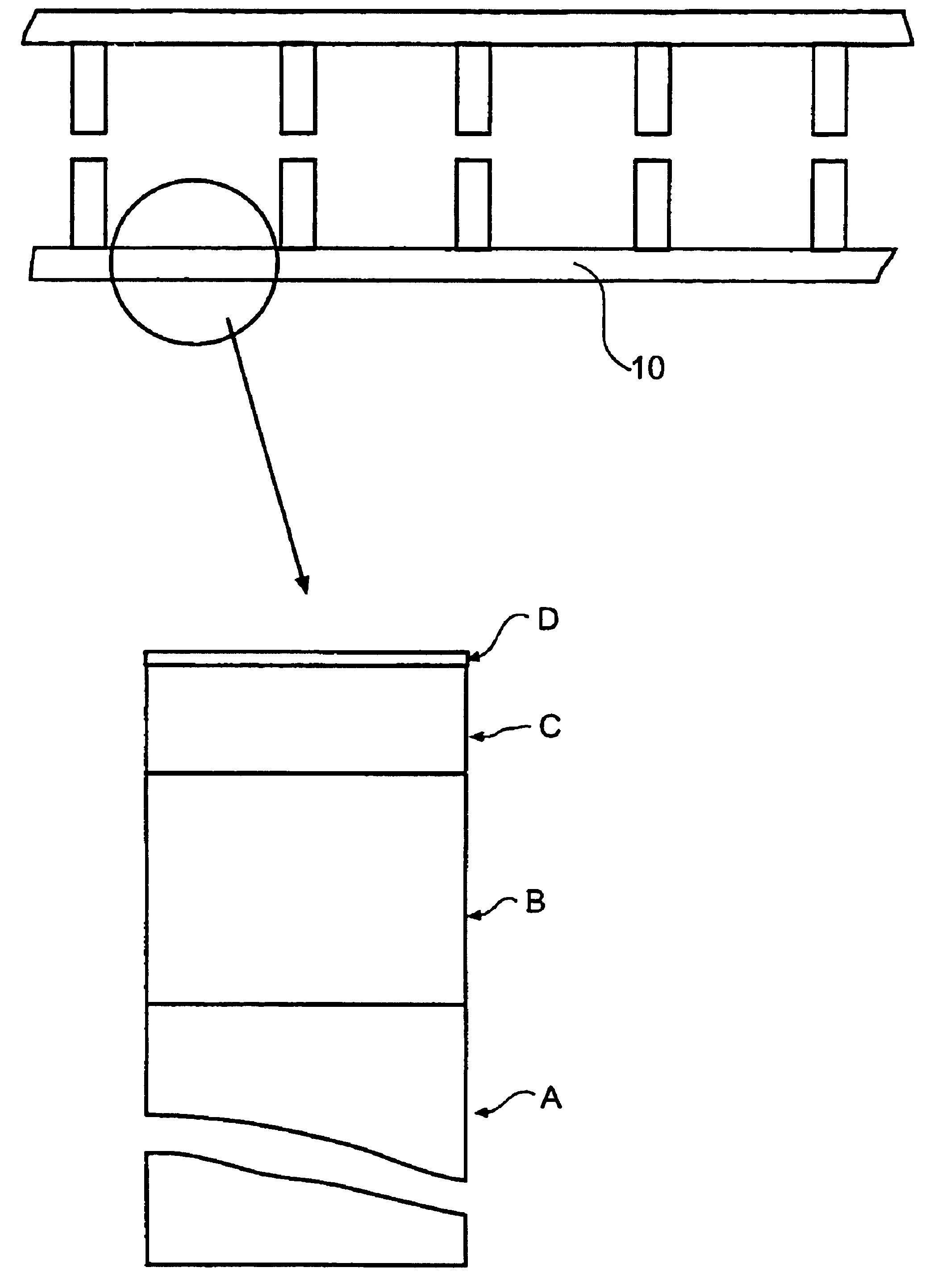
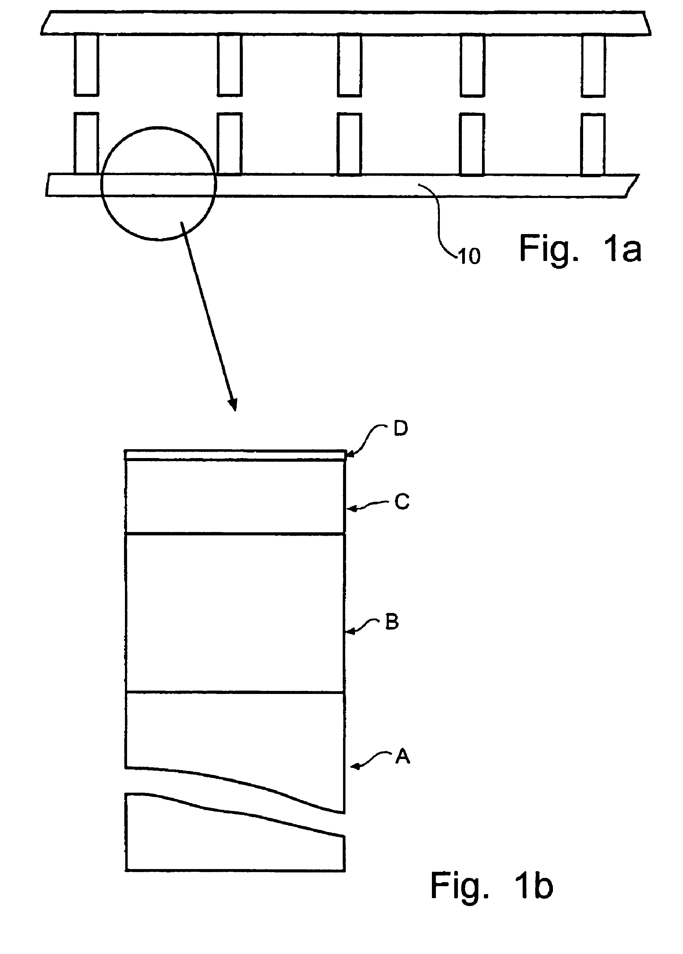
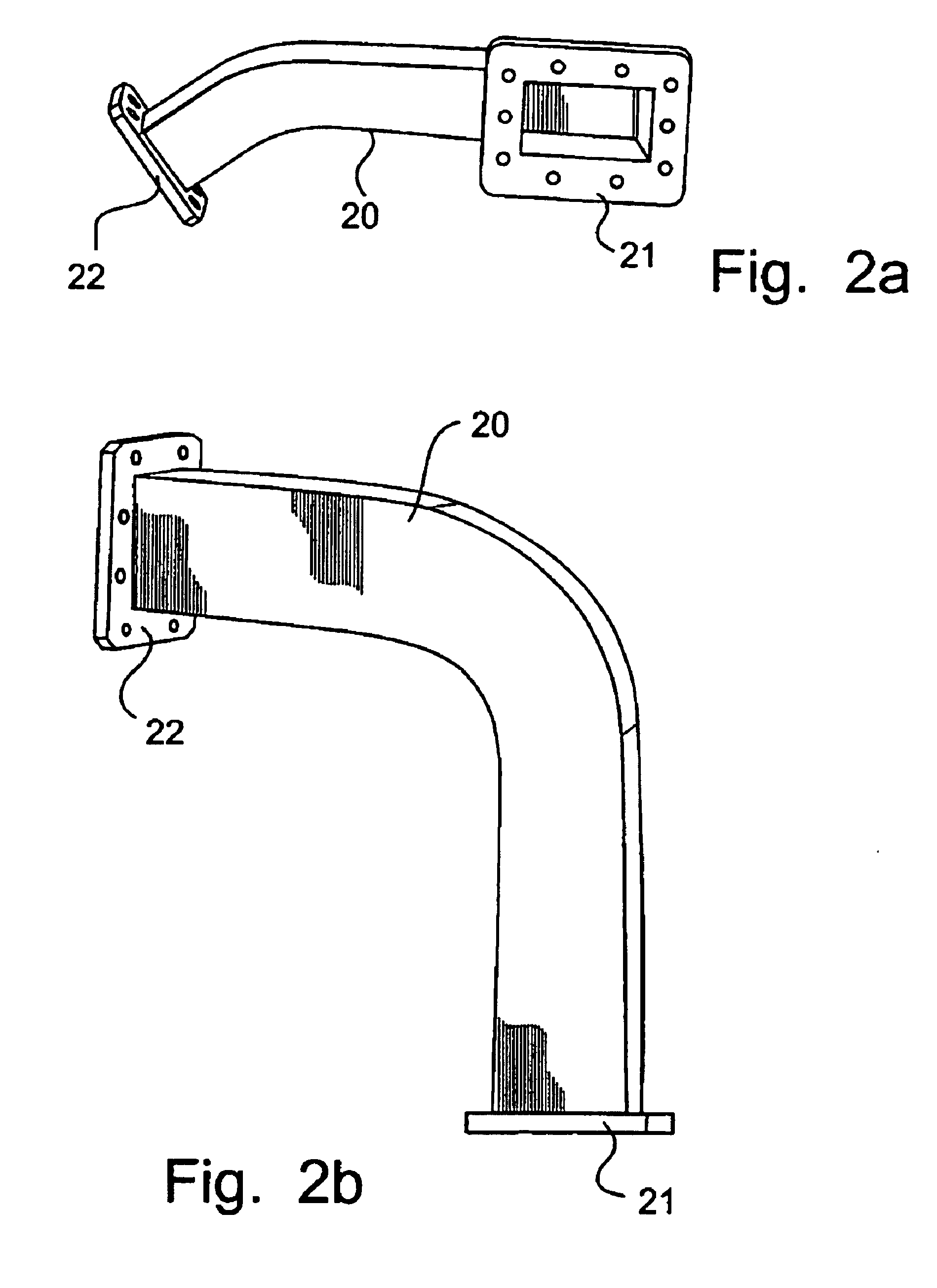
The invention concerns microwave components with a new, improved structure, and a microwave filter, a waveguide and a horn antenna according to the invention will now be described in more detail.

FIG. 1a schematically shows a microwave filter for base stations for mobile telephony according to the invention, comprising a microwave component with a cavity, in this case a filter casing 10, and electric connections, in this case connecting flanges (not shown), arranged on at least one side of said cavity. The microwave filter has a wall construction which is schematically shown in FIG. 1b. The wall comprises on the outside an outer support structure A made of a cast material, such as a castable metal or a ceramic or plastic material. It is, however, also possible to use copper or other materials which are not cast as the outer support structure. The material should be chosen so that the outer support structure has such dimensional tolerance and thermal stability that electric requiremen...


PUM

PropertyMeasurementUnit
sizeaaaaaaaaaa
thicknessaaaaaaaaaa
thicknessaaaaaaaaaa

Abstract

A microwave component with an at least partially enclosed cavity, such as a microwave filter, a waveguide or a horn antenna, includes an outer support structure and an electric layer which is made of pulse-plated silver and which is arranged on the inside of the support structure and faces the cavity. The microwave component further includes a first inner protective layer of chemically precipitated gold, the protective layer being arranged on the electric layer and facing the cavity.

Description

The present invention relates to microwave components with an at least partially enclosed cavity which are suitable for mass production and which satisfy high quality requirements. Examples of such microwave components are microwave filters, waveguides and horn antennas. The invention further relates to a method of manufacturing such components.The manufacture of products of the above-mentioned kind has up to now been very complicated and expensive. Today the manufacture is primarily performed by working aluminium, inter alia by high-speed milling and subsequent surface finishing, such as silver-plating, coating, etc. As a result, it is time-consuming to manufacture each component and a great number of manual operations are necessary. Furthermore, it is difficult to obtain the desired dimensional tolerances and quality of the product by this manufacturing process. Thus, as a rule these products need considerable after-treatment.To solve these problems, the filter casings have, for i...

Claims


Application Information

Patent Timeline
Patent Type & Authority Patents(United States)
IPC IPC(8): H01P1/208H01Q13/00H01P11/00H01P3/12H01P3/00H01P1/20H01Q13/02
CPCH01P1/208H01P3/12H01Q13/0291H01P11/002Y10T29/49016
Inventor BERGMARK, PONTUSREMG.ANG.RD, ANDERS
Owner POLYMER KOMPOSITER I GOTEBORG
Why Eureka
Try Eureka