Multilayered optical thin-film filter, method of designing the same and filter module utilizing the same

a multi-layer, filter technology, applied in multiplex communication, instruments, optical elements, etc., can solve the problems of complex characteristics of multi-layered optical thin-film filters, difficult design and production of filters, and insufficient research and developmen

Inactive Publication Date: 2004-12-14
KYOCERA CORP
View PDF5 Cites 15 Cited by
  • Summary
  • Abstract
  • Description
  • Claims
  • Application Information

AI Technical Summary

Benefits of technology

It is a further object of the present invention to provide an add / drop filter module integrated with the optical filter that is simple in structure and stable in use conditions of heat and the like.
According to the present invention, there may be designed an optical filter with desired band pass filter characteristics, less linear distortion to a passing signal. This eliminates disturbing signals while suppressing linear distortion produced in a desired signal, thereby implementing a multilayered optical thin-film filter capable of maintaining excellent communications quality.
The optical filter module of the present invention has advantages that the magnitude characteristics and the group delay in the passband may be independently controlled, linear distortions of the signal light caused when it is passing through the filter may be restrained to a lower level, and an attenuation pole may be provided in the stop band for creating larger selective characteristics. Further, the optical filter module of the present invention has advantages that there may be obtained a filter with ideal characteristics that has high selectivity and gives less linear distortion to a passing signal regardless of the high selectivity, as a result of which disturbing signals are eliminated while the desired signal is maintained with linear distortions suppressed. Such multilayered optical thin-film filter module may be incorporated in an add / drop system.

Problems solved by technology

Although the above optical filter can be provided in the form of a relatively simple, thermally stable structure at relatively low cost, a method of designing filters with complex characteristics has not yet been established.
Conventionally, multilayered optical thin-film filters themselves have complicated and it is difficult to design and produce a filter considering magnitude and phase group delay time characteristics in the filter.
Also no method for designing filter performance has been known.
Although attempts have been made to achieve narrower band filtering characteristics, the filters have not been considered to reduce linear distortions.
Although conventional filters satisfy wavelength selective characteristics for effective constraint of disturbing signals in the stop bands, large linear distortion has been retained unimproved which deteriorates signal quality.
Particularly, to severe applications for selecting optical signals which are modulated by high speed and signal wavelength spectra and occupy the entire pass band of the filter, dispersion characteristics of the filter cause a required signal to be subjected to a large waveform distortion, with a demodulated signal deteriorating in quality.

Method used


Image

  • Multilayered optical thin-film filter, method of designing the same and filter module utilizing the same
  • Multilayered optical thin-film filter, method of designing the same and filter module utilizing the same
  • Multilayered optical thin-film filter, method of designing the same and filter module utilizing the same

Examples


embodiment 1

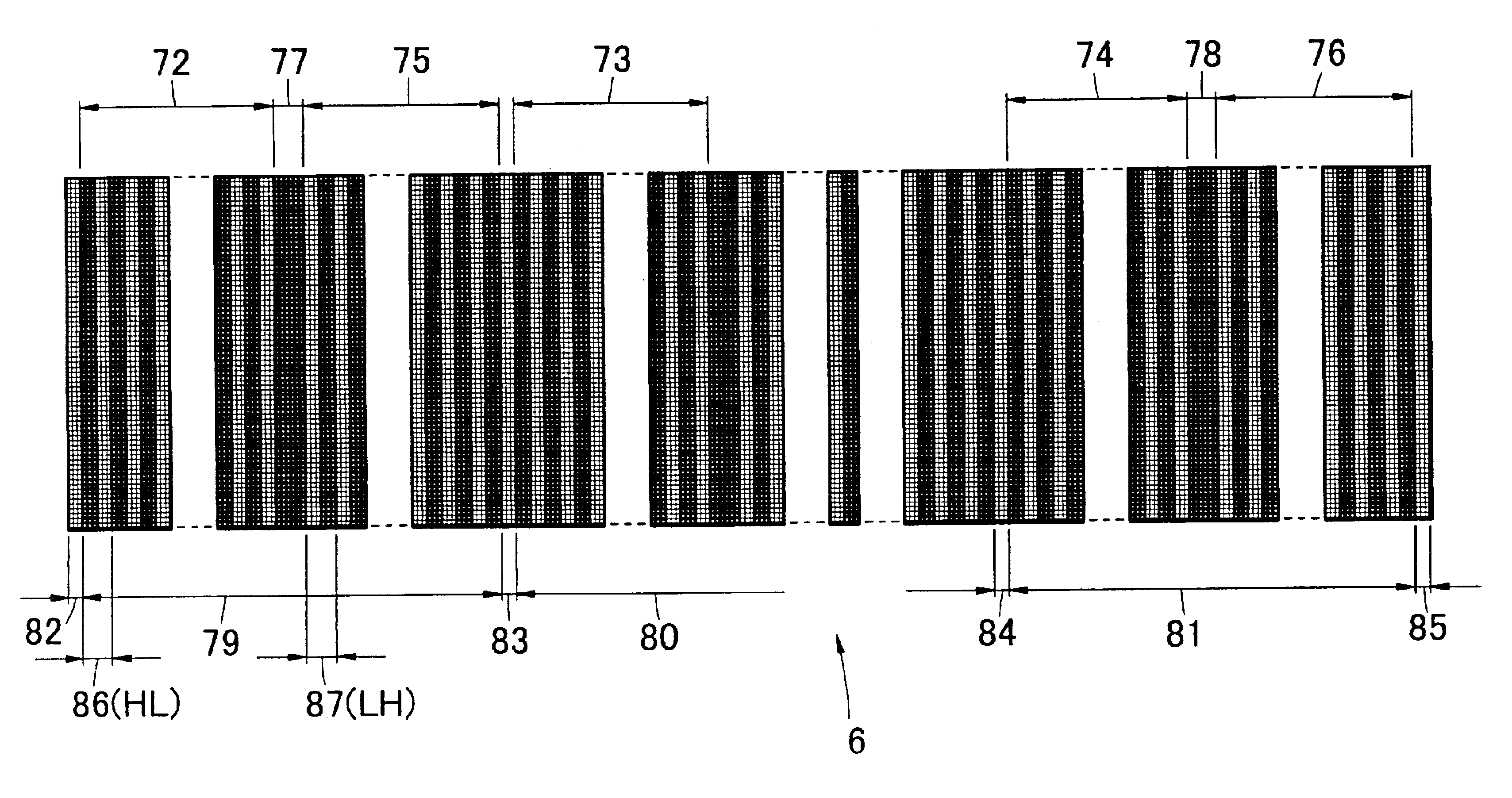
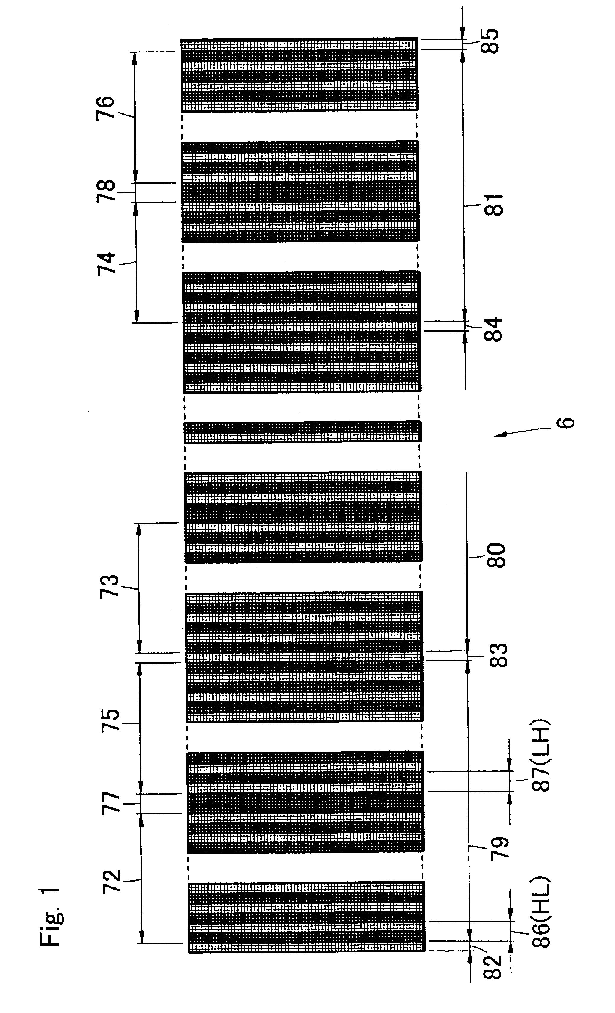
A multilayered optical thin-film filter 6 in the embodiment includes, as components, two types of thin optical films having substantially the same thickness .lambda..sub.0 / 4 of a quarter wavelength at the passing center .lambda..sub.0 having different two refractive indices.

In first and second reflector layers of this filter, unit optical thin films are used which are made up of a pair of two layers, which are, as shown in FIG. 15, composed of an optical thin film H with a high refractive index and a thickness of a quarter wavelength .lambda..sub.0 at the passing center and an optical thin film L with a low refractive index and a thickness of .lambda..sub.0 / 4 as a basic component.

A first unit reflector layer 86 is, as shown in FIG. 15, a pair of two layers obtained by layering the optical thin film H with a high refractive index and the optical thin film L with a low refractive index in this order (HL) (for example, seen from a multilayering substrate). A first reflector layer 7 i...

embodiment 2

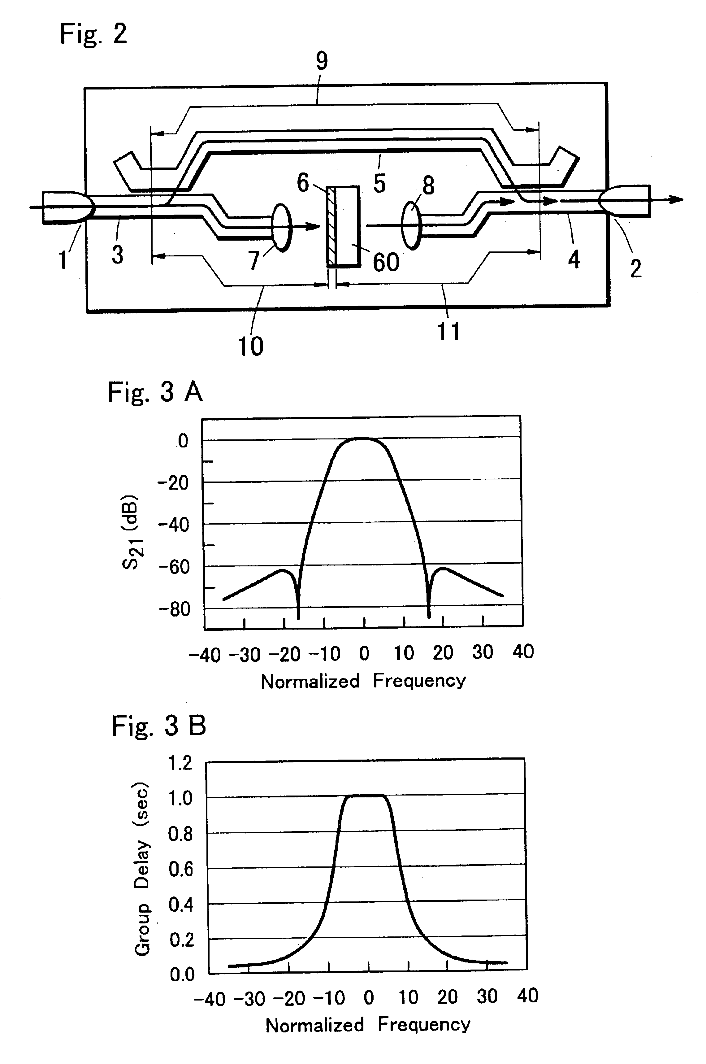
FIG. 2 is a view showing an optical filter module, which is composed of a multilayered optical thin-film filter 6 and an optical path 5 as a phase shifter that is branched and joined in parallel with the multilayered optical thin-film filter 6.

In the present embodiment, an input port and an output port are each connected to optical couplers, and branching terminals of these two optical couplers are connected to the multilayered optical thin-film filter 6 and the optical path 5.

An optical input signal at port 1 is branched off to two signals by a coupler 3: one travels through an optical path 5 with an electrical length of 9 and joins with the other in a coupler 4, while the other is collimated by a collimate optical system 7, subjected to wavelength selection by the multilayered optical thin-film filter 6, passes again through a collimate optical system 8, and then joins with the one in the coupler 4. The joined signal is fed from port 2.

With a wavelength of a passing signal being ....


PUM


Abstract

In a multilayered optical thin-film filter having multiple quarter wavelength thick optical thin films with different refractive indices, the filter includes a plurality of unit cavities that are stacked multiple times via a connection layer, each unit cavity including a first reflector layer, a spacer layer in contact with the first reflector layer, and a second reflector layer in contact with the spacer layer. The first reflector layer is a layered body and the second reflector layer is a layered body. The spacer layer is a multilayered optical thin film with a high refractive index obtained by layering even number of films, or is composed of a multilayered optical thin film with a low refractive index. The connection layer is a multilayered optical thin film with a low refractive index obtained by layering odd number of films.

Description

1. Field of the InventionThe present invention relates to a multilayered optical thin-film filter with improved transmission phase characteristics for an optical band pass filter, particularly to an optical filter for use in wavelength division multiplexing (WDM) photonic networks (optical fiber communications networks). The present invention relates to a method of designing such an optical filter, and also to an optical filter module including such an optical filter.2. Prior ArtIn wavelength division multiplexing (WDM) photonic networks, there have been used optical add / drop multiplexers (ADM) for multiplexing a number of wavelength light signals in to an transmission optical fiber and for separating the summed signals into individual wavelengths, the function of which is implemented by use of an optical filter for wavelength segmentation.As an example of such filters which have conventionally been used, FIG. 21 shows a multilayered optical thin-film filter which is a band-pass fil...

Claims


Application Information

Patent Timeline
Patent Type & Authority Patents(United States)
IPC IPC(8): G02B5/28G02B6/12G02B6/34H04J14/02
CPCG02B5/288G02B6/12007G02B6/2938G02B6/2937H04J14/0201
Inventor TAKEDA, SHIGEKI
Owner KYOCERA CORP
Why Eureka
Try Eureka