Exposure method and apparatus

a technology of exposure method and exposure apparatus, which is applied in the direction of mechanical control devices, instruments, manual control with single controlling member, etc., can solve the problems of inconvenience, inability to increase throughput so much, and inability to increase throughpu

Inactive Publication Date: 2004-12-28
NIKON CORP
View PDF22 Cites 15 Cited by
  • Summary
  • Abstract
  • Description
  • Claims
  • Application Information

AI Technical Summary

Problems solved by technology

Among the double-wafer stages of the conventional exposure apparatuses as described above, as for the arrangement in which the guide for one axis of the orthogonal axes is used for both of the two movable stages, an inconvenience arises such that the influence of vibration of the second movable stage tends to be

Method used


Image

  • Exposure method and apparatus
  • Exposure method and apparatus
  • Exposure method and apparatus

Examples


Embodiment Construction

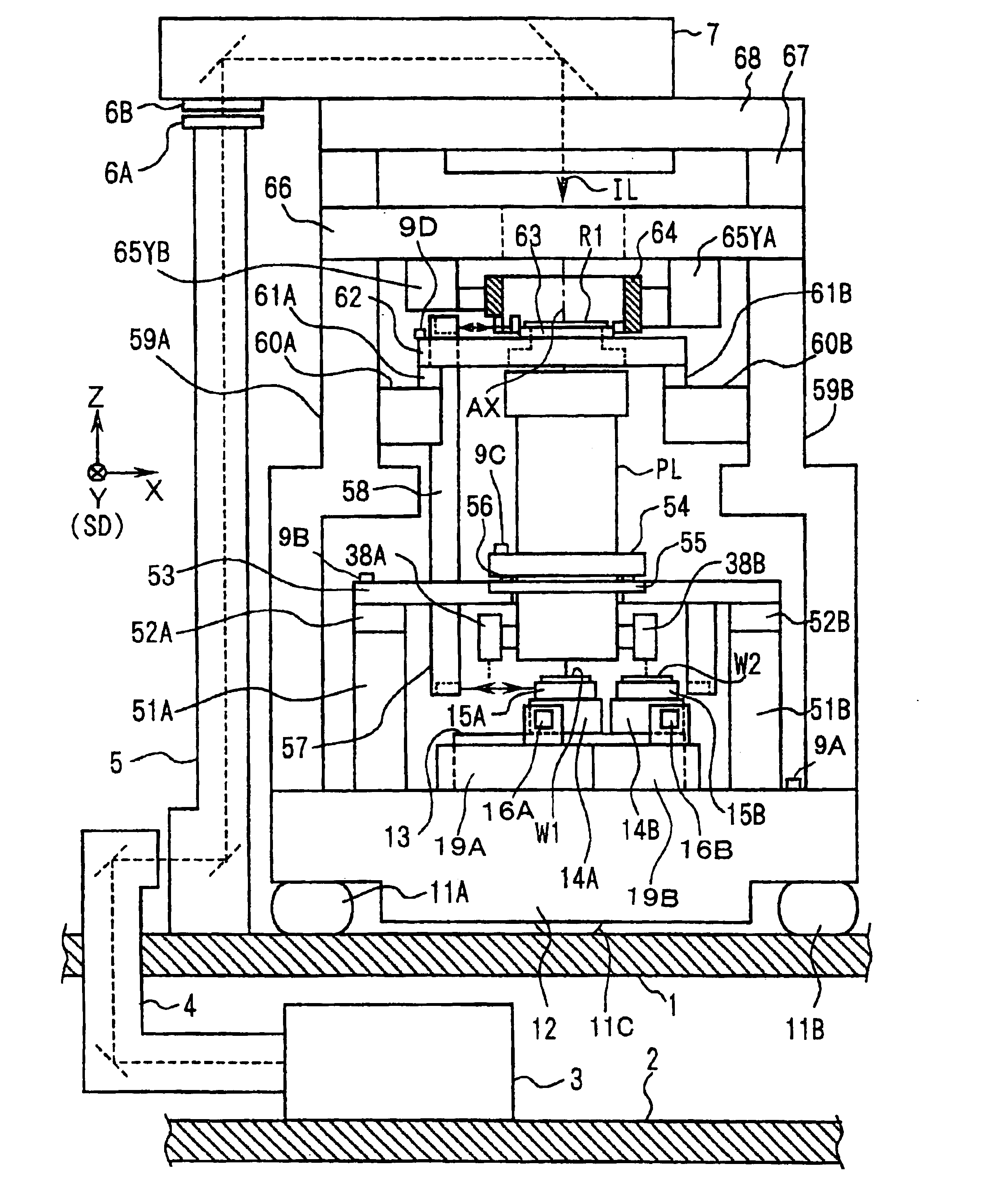
An exemplary preferred embodiment of the present invention will be explained below with reference to the drawings. In this embodiment, the present invention is applied to a projection exposure apparatus based on the scanning exposure system of the step-and-scan system.

FIG. 1 shows the projection exposure apparatus according to this embodiment. With reference to FIG. 1, for example, most parts of the projection exposure apparatus of this embodiment are installed on a floor 1 in a clean room in a semiconductor-manufacturing factory. An exposure light source 3 of the projection exposure apparatus is installed on a floor 2 in a semi-clean room in a machine room disposed thereunder. Those usable as the exposure light source 3 include, for example, an excimer laser light source such as KrF (wavelength: 248 nm) and ArF (wavelength: 193 nm), an F.sub.2 laser light source (wavelength: 157 nm), a Kr.sub.2 laser light source (wavelength: 146 nm), a high harmonic wave generator of a YAG laser, ...


PUM


Abstract

There are provided an exposure method and an exposure apparatus in which the influence of vibration is not mutually transmitted so much when two movable stages are used. X axis sliders (19A, 20A) are arranged movably in the X direction on both sides in the Y direction of a wafer base (13). A first Y axis slider (16A) is arranged movably in the Y direction for the X axis sliders (19A, 20A). A first wafer stage (WST1) is arranged movably in the Y direction (scanning direction) along the Y axis slider (16A). X axis sliders (19B, 20B) are arranged in parallel to the X axis sliders (19A, 20A). A second Y axis slider (16B) is arranged for the X axis sliders (19B, 20B). A second wafer stage (WST2) is arranged movably along the Y axis slider (16B). When exposure is performed on the side of the first wafer stage (WST1), wafer exchange or wafer alignment is performed on the side of the second wafer stage (WST2).

Description

1. Field of the InventionThe present invention relates to an exposure method and an exposure apparatus to be used, for example, when a mask pattern is transferred onto a substrate in the lithography step for producing, for example, semiconductor elements, liquid crystal display elements, plasma display elements, and thin film magnetic heads. In particular, the present invention relates to an exposure apparatus in which a vibration-preventive control is adopted.2. Description of the Related ArtA high exposure accuracy is required for the exposure apparatus of the full field exposure type (stepper type) or the scanning exposure type (for example, those based on the step-and-scan system) to be used when the semiconductor element or the like is produced. Therefore, in the exposure apparatus, an arrangement, which makes it possible to perform highly accurate positioning or highly accurate scanning, is adopted for a reticle stage on which a reticle as a mask is placed and positioned and f...

Claims


Application Information

Patent Timeline
IPC IPC(8): G03F7/20G03F9/00
CPCG03F7/70358G03F7/70716G03F7/70725G03F9/7003G03F9/7011G03F7/70733Y10T74/20207Y10T74/20201
Inventor NISHI, KENJI
Owner NIKON CORP
Why Eureka
Try Eureka