
Cutting tool and tool with holder

a technology of cutting tools and tools, applied in combination recording, recording information storage, turning machine accessories, etc., can solve problems such as unusual wear and damage, and achieve the effect of favorable milling and grooving

Inactive Publication Date: 2005-01-04
NGK SPARK PLUG CO LTD
View PDF7 Cites 28 Cited by
  • Summary
  • Abstract
  • Description
  • Claims
  • Application Information

AI Technical Summary

Benefits of technology

The present invention has been accomplished in view of the foregoing, and an object of the invention is to provide a cutting tool coated with a hard coating capable of reliably and favorably exhibiting cutting performance, such as adhesion resistance and wear resistance, as well as a tool with a holder incorporating the same.
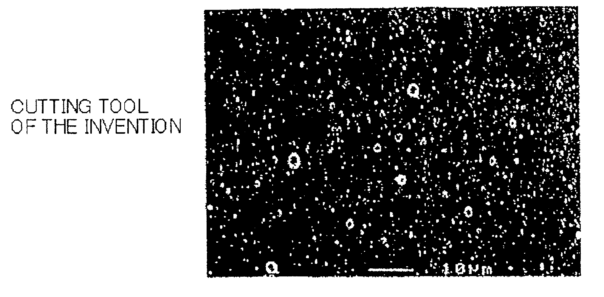
To achieve the above object, the present inventors have studied conditions for allowing a TiAlN-type PVD film to reliably and favorably maintain cutting performance and have found that through control of the size and amount of coarse grains within certain respective ranges and through determination of surface smoothness by use of surface roughness, wear resistance can be stabilized, thus leading to achievement of the present invention.(1) According to the invention, a cutting tool comprises a substrate and a TiAlN-type hard coating formed on the substrate. The hard coating has a thickness of 1 to 5 μm, and coarse grains present in the hard coating and having a size not less than the thickness of the hard coating occupy an area percentage not greater than 5% by area.
The size of the coarse grains (whose amount is specified in terms of % by area) is specified as being not less than the thickness of the hard coating on the substrate surface for the following reason. When a grain having a size not less than the coating thickness drops off during cutting, exposure of the substrate becomes highly likely. When the substrate is exposed, joining through fusion and exfoliation arise, resulting in the occurrence of unusual wear. In other words, when coarse grains have a size less than the thickness of the hard coating, dropping-off of a coarse grain does not lead to exposure of the substrate, whereby an impairment in cutting performance can be restrained. Therefore, the size of the coarse grains to be limited in amount is specified as being not less than the thickness of the hard coating.
The invention of this aspect is drawn to an embodiment of a material used to form the substrate of the cutting tool. Use of such a material enables high cutting performance.(4) According to a fourth preferred aspect of the invention, in the cutting tool as described above, the hard coating is a vapor deposition film formed through arc-ion-type physical vapor deposition.
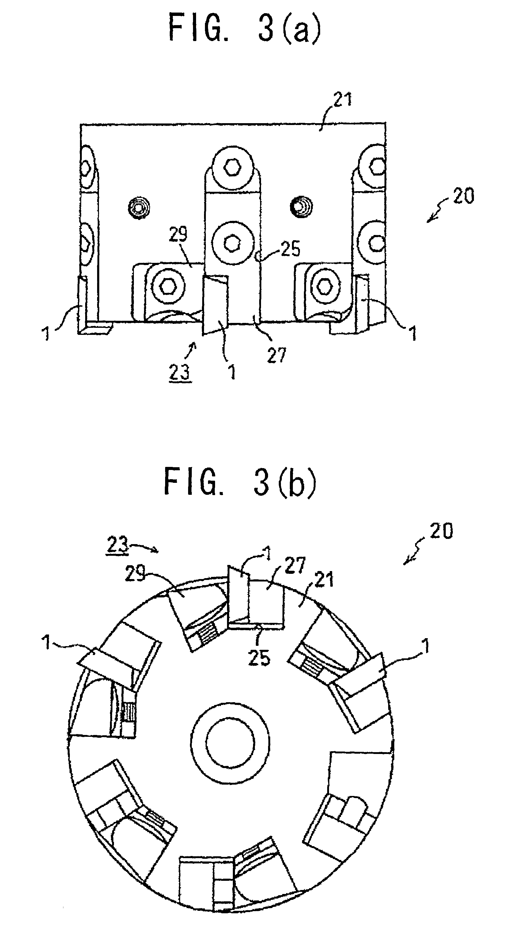
The present invention contemplates a tool with a holder for milling or a tool with a holder for grooving. By use of the tools with a holder, milling and grooving can be favorably performed.

Problems solved by technology

When the thickness exceeds 5 μm, residual stress of the coating increases, and thus the coating fractures with a resultant impairment in cutting performance.
When the substrate is exposed, joining through fusion and exfoliation arise, resulting in the occurrence of unusual wear.

Method used


Image

  • Cutting tool and tool with holder
  • Cutting tool and tool with holder
  • Cutting tool and tool with holder

Examples


Embodiment Construction

Illustrative, non-limiting examples of a cutting tool and a tool with a holder according to the present invention are described below.a) First, a cutting tool of the present embodiment will be described.

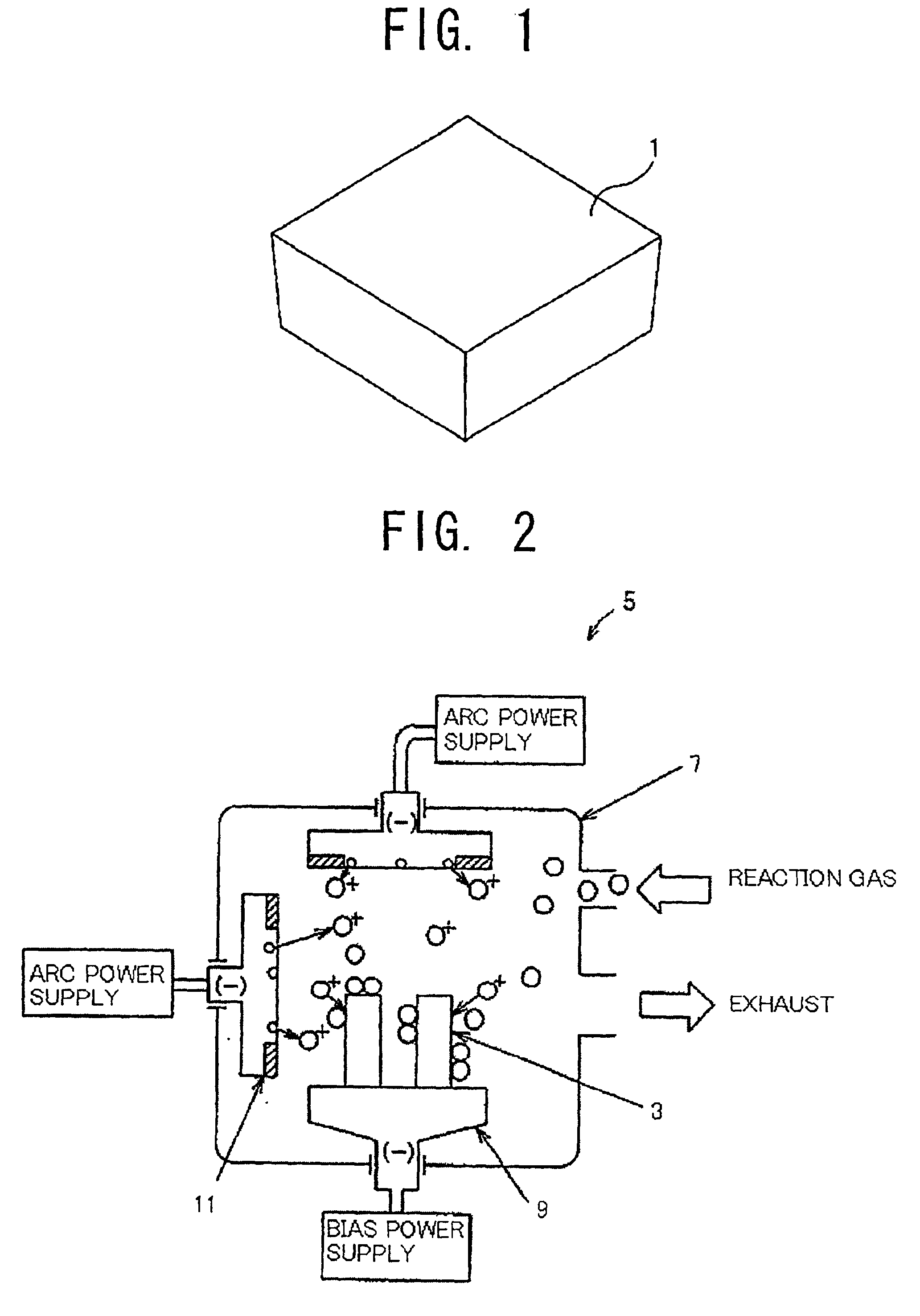
As shown in FIG. 1, a cutting tool 1 of the present embodiment is a throwaway tip configured such that a hard coating is formed on the surface of a substrate 3 (see FIG. 2). The substrate 3 may be formed of, for example, a hard material of cemented carbide (WC-Co-type cemented carbide) equivalent to JIS K10, which is defined in JIS B 4053 (1989), and polished into the shape of ISO SPGN120312. Specifically, the cutting tool 1 is a plate-shaped positive tip whose rake face (the main surface side), which is the upper face in FIG. 1, is wider than the opposite face. The surface of the substrate 3 is coated with a hard coating having a thickness ranging from 1 μm to 5 μm (e.g., 3 μm), formed of a TiAlN material, for example, (Ti,Al)N, and having a Ti / Al ratio of 1.

According to the present...


PUM

PropertyMeasurementUnit
thicknessaaaaaaaaaa
surface roughnessaaaaaaaaaa
surface roughness Rzaaaaaaaaaa

Abstract

A cutting tool 1 includes a hard coating formed on the surface of a substrate formed of, for example, a hard material of cemented carbide (WC-Co-type cemented carbide) equivalent to JIS K10 and polished into the shape of ISO SPGN120312. The cutting tool 1 has a plate-shape with a rake face (the main surface side) that is wider than the opposite face. The hard coating has a thickness in the range of from 1 μm to 5 μm, is formed of a TiAlN material, and has a Ti / Al ratio of 1. Coarse grains present in the hard coating and having a size not less than coating thickness occupy an area percentage not greater than 5% by area. The hard coating has a surface roughness Ra of not greater than 0.1 μm and a surface roughness Rz of not greater than 1 μm.

Description

BACKGROUND OF THE INVENTION1. Field of the InventionThe present invention relates to a cutting tool coated with a hard coating exhibiting excellent adhesion resistance and excellent wear resistance and to a tool with a holder incorporating the same.2. Description of the Related ArtConventionally, an arc-ion-type PVD process has been frequently employed for PVD coating with a TiAlN material (coating through physical vapor deposition), since high energy is required for ionization of a TiAl metal and since the process has the advantage, among others, that a coating layer of excellent adhesion is readily obtained.However, in some cases, this process permits the generation of coarse TiAl grains which is caused by a local concentration of arc derived from the non-uniform surface condition of a TiAl target or a non-uniform generation of arc. As a result, the deposition of coarse TiAlN grains occurs.Some coarse grains have a size of several micrometers to several tens of micrometers. When s...

Claims


Application Information

Patent Timeline
Patent Type & Authority Patents(United States)
IPC IPC(8): C23C14/06C23C30/00B23C5/20B23B27/14
CPCC23C14/0641C23C30/005Y10T407/23Y10T428/24372Y10T428/26Y10T428/24355Y10T407/27Y10T407/19Y10T83/9319C23C14/06
Inventor KATO, HIDEKI
Owner NGK SPARK PLUG CO LTD
Learn More