PTC circuit protection devices

a protection device and circuit technology, applied in the direction of resistor chip manufacture, resistor details, positive temperature coefficient thermistors, etc., can solve the problems of large power dissipation of ptc devices, greater heat generation rate of devices, and unstable ptc devices. , to achieve the effect of more susceptible to mounting

Inactive Publication Date: 2005-01-04
LITTELFUSE INC
View PDF24 Cites 37 Cited by
  • Summary
  • Abstract
  • Description
  • Claims
  • Application Information

AI Technical Summary

Benefits of technology

In a preferred embodiment and in order to buildup the end terminations to handle higher current capacities, a second conductive layer is applied to the laminate prior to removing portions of the layer. Further, in order to make the devices more s

Problems solved by technology

At this point, a great deal of power is dissipated in the PTC device and the PTC device becomes unstable (i.e., the rate at which the device generates heat is greater than the rate at which the device can lose heat to its surroundings).
This power dissipation only occurs for a shor

Method used


Image

  • PTC circuit protection devices
  • PTC circuit protection devices
  • PTC circuit protection devices

Examples


first embodiment

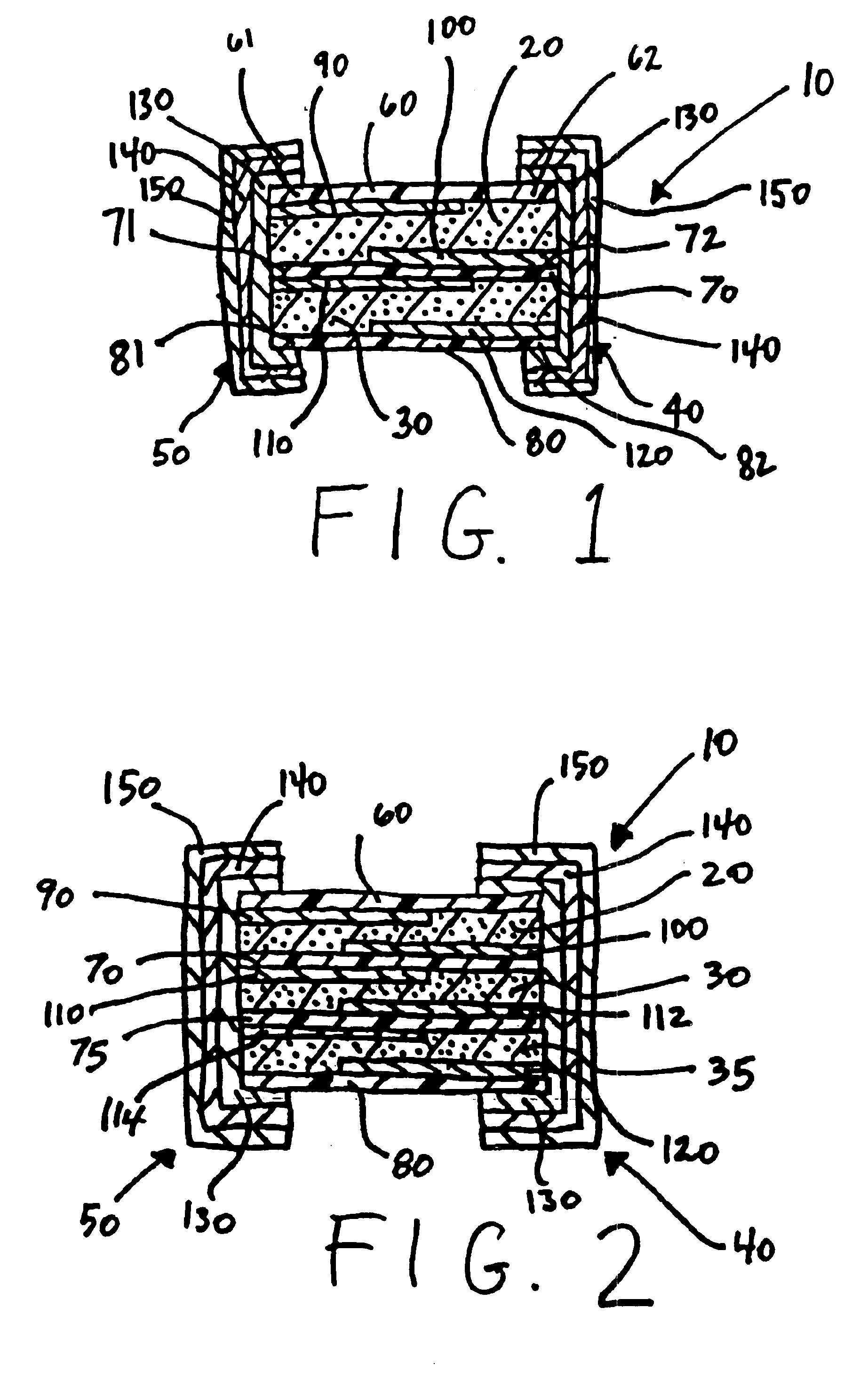
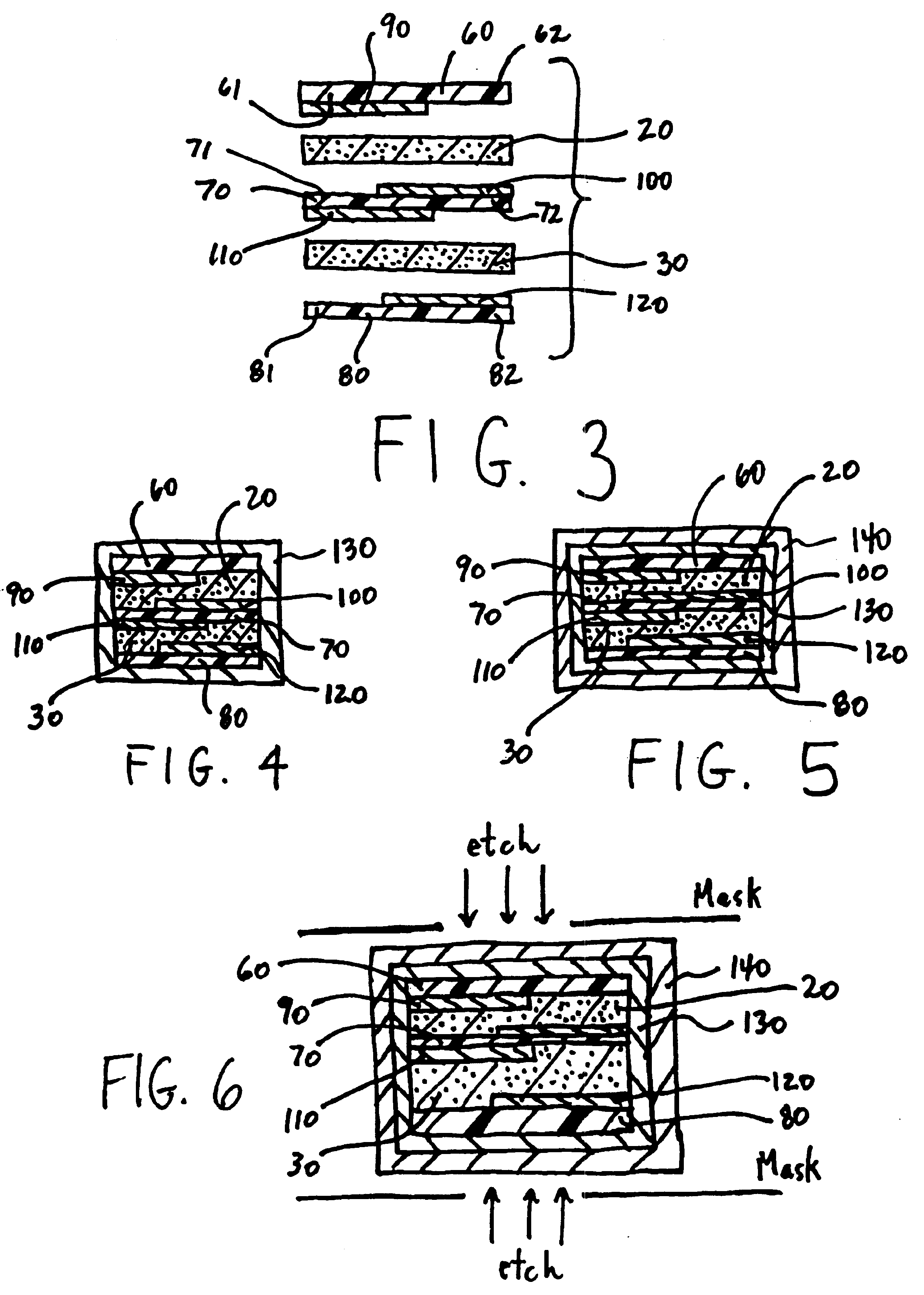
FIG. 1 illustrates an electrical device 10 according to the present invention. The device 10 is comprised of first and second PTC elements 20,30 electrically connected in parallel between first and second end terminations 40,50. The first and second PTC elements 20,30 are interposed between first, second and third substrates 60,70,80.

Generally, the PTC elements 20,30 are composed of a PTC composition comprised of a polymer component and a conductive filler component. The polymer component may comprise a polyolefin having a crystallinity of at least 40%. Suitable polymers include polyethylene, polypropylene, polybutadiene, polyethylene acrylates, ethylene acrylic acid copolymers, and ethylene propylene copolymers. In a preferred embodiment, the polymer component comprises polyethylene and maleic anhydride, e.g., Fusabond™ brand manufactured and sold by DuPont. The conductive filler is dispersed throughout the polymer component in an amount sufficient to ensure that the composition ex...

second embodiment

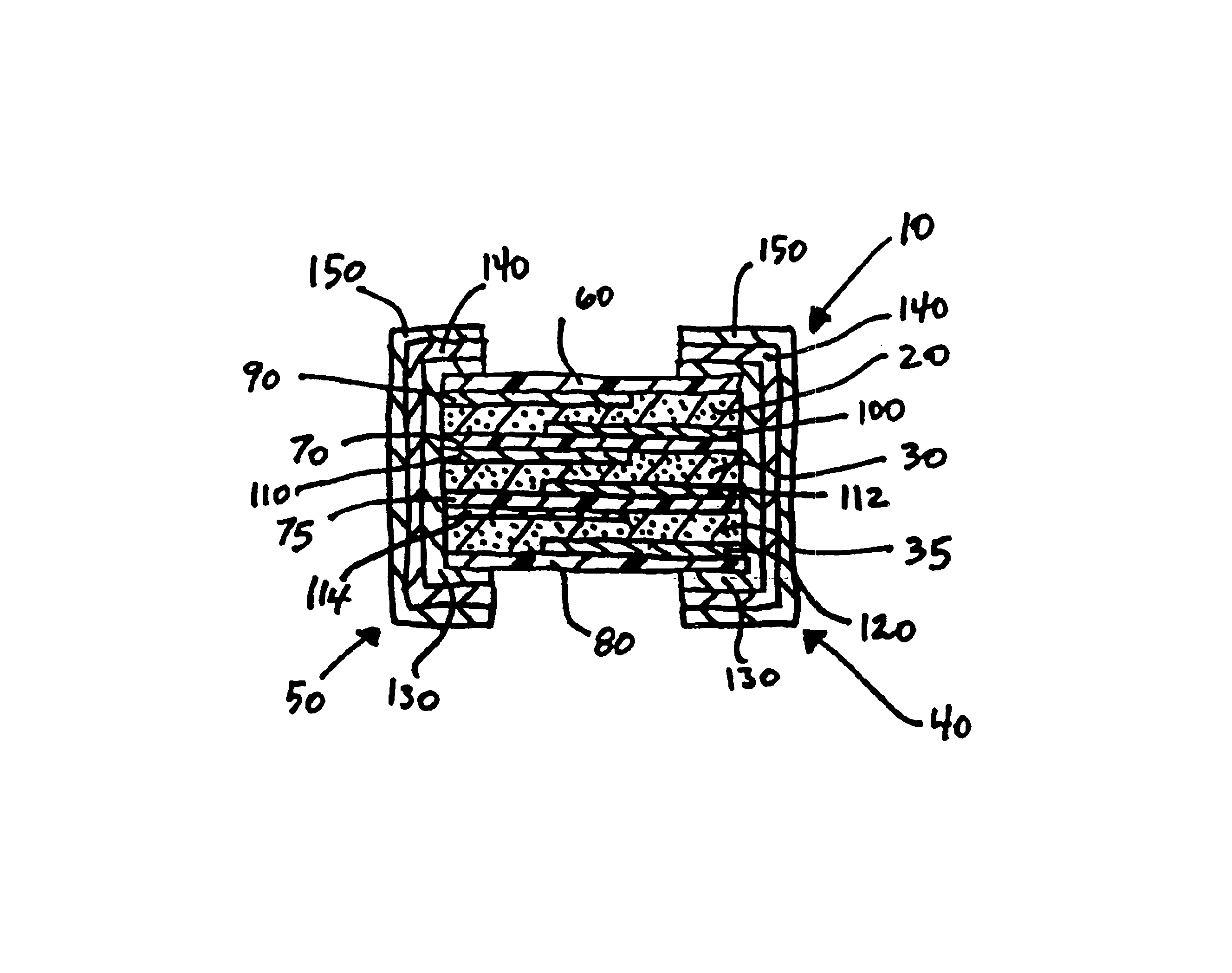
Referring now to FIG. 2, in a second embodiment the device 10 is comprised of three PTC elements 20,30,35 laminated between four substrates 60,70,75,80. The additional substrate, illustrated in FIG. 2 by reference numeral 75, has a similar offset electrode configuration as substrate 70, i.e., a first electrode 112 is formed on a first (top) surface and extends to one end but not the other end of the substrate 75, and a second electrode 114 is formed on a second surface (bottom) and extends to the opposite end of the substrate 75 as does the first electrode 112. In the embodiment illustrated in FIG. 2, the first end termination 40 is in direct contact with electrodes 100,112,120 but not electrodes 90,110,114, while the second end termination 50 is in direct contact with electrodes 90,110,114 but not electrodes 100,112,120. Accordingly, the PTC elements 20,30,35 are electrically connected in parallel between the wrap-around end terminations 40,50 and provide the device 10 with a highe...


PUM


Abstract

An electrical circuit protection device with three supporting substrates, two PTC elements, and first and second end terminations. The first and third substrates have an electrode formed on a first surface thereof. The second substrate has electrodes formed on both surfaces thereof. The first PTC element is laminated between the first and second substrates, electrically connecting the
first electrodes formed on the first and second substrates. The second PTC element is laminated between the second and third substrates, electrically connecting the second electrode formed on the second substrate and the first electrode formed on the third substrate. The end terminations wraps around opposite ends of the device. The first end termination is in electrical contact with the first electrodes formed on the second and third substrates and the second end termination is in electrical contact with the first electrode formed on the first substrate and the second electrode formed on the second substrate. The PTC elements are electrically connected in parallel between the end terminations. The multi-layered configuration allows for an increased electrical rating without increasing the overall footprint, i.e., length and width, of the device.

Description

TECHNICAL FIELDThe present invention relates generally to a surface mountable electrical circuit protection device and specifically to a multi-layer PTC configuration for higher rated devices.BACKGROUND OF THE INVENTIONIt is well known that the resistivity of many conductive materials change with temperature. Resistivity of a positive temperature coefficient (“PTC”) material increases as the temperature of the material increases. Many crystalline polymers, made electrically conductive by dispersing conductive fillers therein, exhibit this PTC effect. These polymers generally include polyolefins such as polyethylene, polypropylene and ethylene / propylene copolymers. Certain doped ceramics such as barium titanate also exhibit PTC behavior.At temperatures below a certain value, i.e., the critical or switching temperature, the PTC material exhibits a relatively low, constant resistivity. However, as the temperature of the PTC material increases beyond this point, the resistivity sharply ...

Claims


Application Information

Patent Timeline
IPC IPC(8): H01C17/00H01C7/02H01C1/14
CPCH01C1/1406H01C17/006H01C7/027H01C7/021
Inventor MINERVINI, ANTHONY D.LUCIANO, HONORIO S.
Owner LITTELFUSE INC
Why Eureka
Try Eureka