Method for optimizing an illumination source using full resist simulation and process window response metric

Inactive Publication Date: 2005-01-04
ASML NETHERLANDS BV
View PDF14 Cites 45 Cited by
  • Summary
  • Abstract
  • Description
  • Claims
  • Application Information

AI Technical Summary

Benefits of technology

Although specific reference may be made in this text to the use of the apparatus according to the invention in the manufacture of ICs, it should be explicitly understood that such an apparatus has many other possible applications. For example, it may be employed in the manufacture of integrated optical systems, guidance and detection patterns for

Problems solved by technology

The resolution limit of currently available lithographic techniques is being reached due to a decrease in the depth of focus, difficulty in the design of lenses and complexities in the lens fabrication technology.
Such an approach results in a significant loss in intensity available to the mask, lowering throughput and making the approach less than desirable.
Additionally, the four circular openings need to be designed specifically for certain mask geometry and pitch and do not improve the performance of other geometry sizes and sp

Method used


Image

  • Method for optimizing an illumination source using full resist simulation and process window response metric
  • Method for optimizing an illumination source using full resist simulation and process window response metric
  • Method for optimizing an illumination source using full resist simulation and process window response metric

Examples


Embodiment Construction

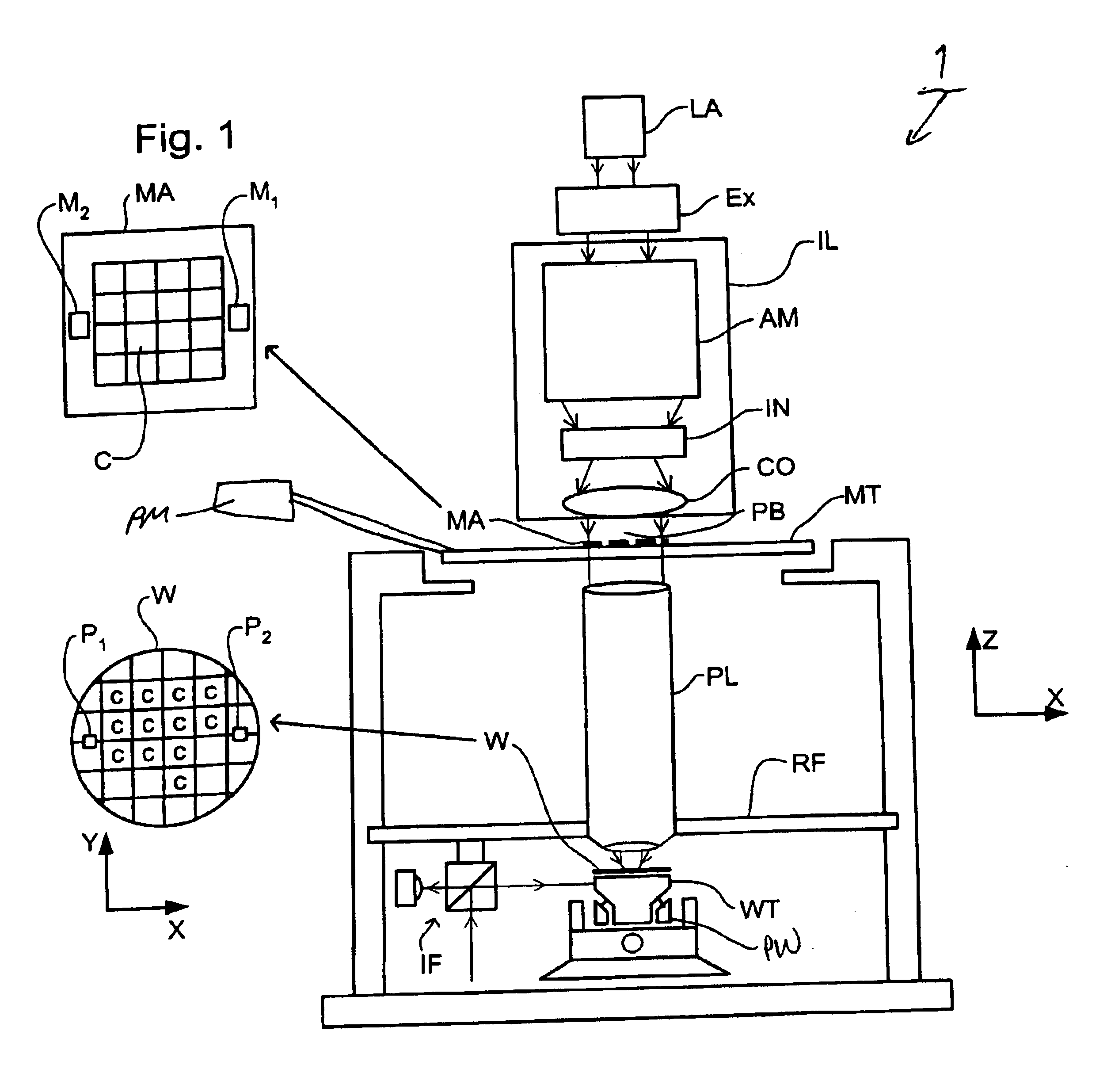
FIG. 1 schematically depicts a lithographic projection apparatus 1 according to an embodiment of the invention. The apparatus includes a radiation system Ex, IL constructed and arranged to supply a projection beam PB of radiation (e.g. UV or EUV radiation, such as, for example, generated by an excimer laser operating at a wavelength of 248 nm, 193 nm or 157 nm, or by a laser-fired plasma source operating at 13.6 nm). In this embodiment, the radiation system also comprises a radiation source LA. The apparatus also includes a first object (mask) table MT provided with a mask holder constructed and arranged to hold a mask MA (e.g. a reticle), and connected to a first positioning device PM to accurately position the mask with respect to a projection system or lens PL; a second object (substrate) table WT provided with a substrate holder constructed and arranged to hold a substrate W (e.g. a resist-coated silicon wafer), and connected to a second positioning device PW to accurately posit...


PUM


Abstract

A method for optimizing the illumination conditions of a lithographic apparatus by computer simulation using full resist calculation, the lithographic apparatus comprising an illuminator, a projection system, and a mask having a pattern to be printed in a layer of photoresist material formed on a substrate. This method includes defining a lithographic 0problem, which may include a lithographic pattern to be printed on a wafer; choosing a resist model of a resist process to be used to print a pattern in the layer of photoresist material; selecting a grid of source points in a pupil plane of the illuminator; calculating separate responses for individual source points, each of the responses representing a result of a single or series of simulations using the resist model; and adjusting an illumination arrangement based on analysis of accumulated results of the separate calculations.

Description

BACKGROUND OF THE INVENTION1. Field of the InventionThe present invention relates to a method for optimizing an illumination source of a lithographic apparatus using full resist simulation.2. Description of the Related ArtThe term “patterning device” as here employed should be broadly interpreted as referring to a device that can be used to endow an incoming radiation beam with a patterned cross-section, corresponding to a pattern that is to be created in a target portion of the substrate. The term “light valve” can also be used in this context. Generally, the pattern will correspond to a particular functional layer in a device being created in the target portion, such as an integrated circuit or other device. An example of such a patterning device is a mask. The concept of a mask is well known in lithography, and it includes mask types such as binary, alternating phase shift, and attenuated phase shift, as well as various hybrid mask types. Placement of such a mask in the radiation...

Claims


Application Information

Patent Timeline
IPC IPC(8): G03F7/20
CPCG03F7/701G03F7/705G03F7/70108
Inventor HANSEN, STEVEN GEORGE
Owner ASML NETHERLANDS BV
Why Eureka
Try Eureka