This helps you quickly interpret patents by identifying the three key elements:
Problems solved by technology
Method used
Benefits of technology
Benefits of technology
An object of the present invention is to provide an absolute humidity sensor having an improved sensitivity and high response time.
Another object of the present invention is to provide an absolute humidity sensor having a compact size and simple process steps to facilitate mass production.
Problems solved by technology
Since the background art humidity sensor uses an element as a ceramicthermistor, heat capacity is great, and thus, sensitivity is low.
Also, response time is slow and the size of the sensor becomes greater.
For this reason, the fabrication process steps are complicated and the number of the process steps increases.
Also, the cost is expensive and mass production is disadvantageous.
Method used
Image
Click on the blue label to locate the original text in one second.
Reading with bidirectional positioning of images and text.
Examples
first embodiment
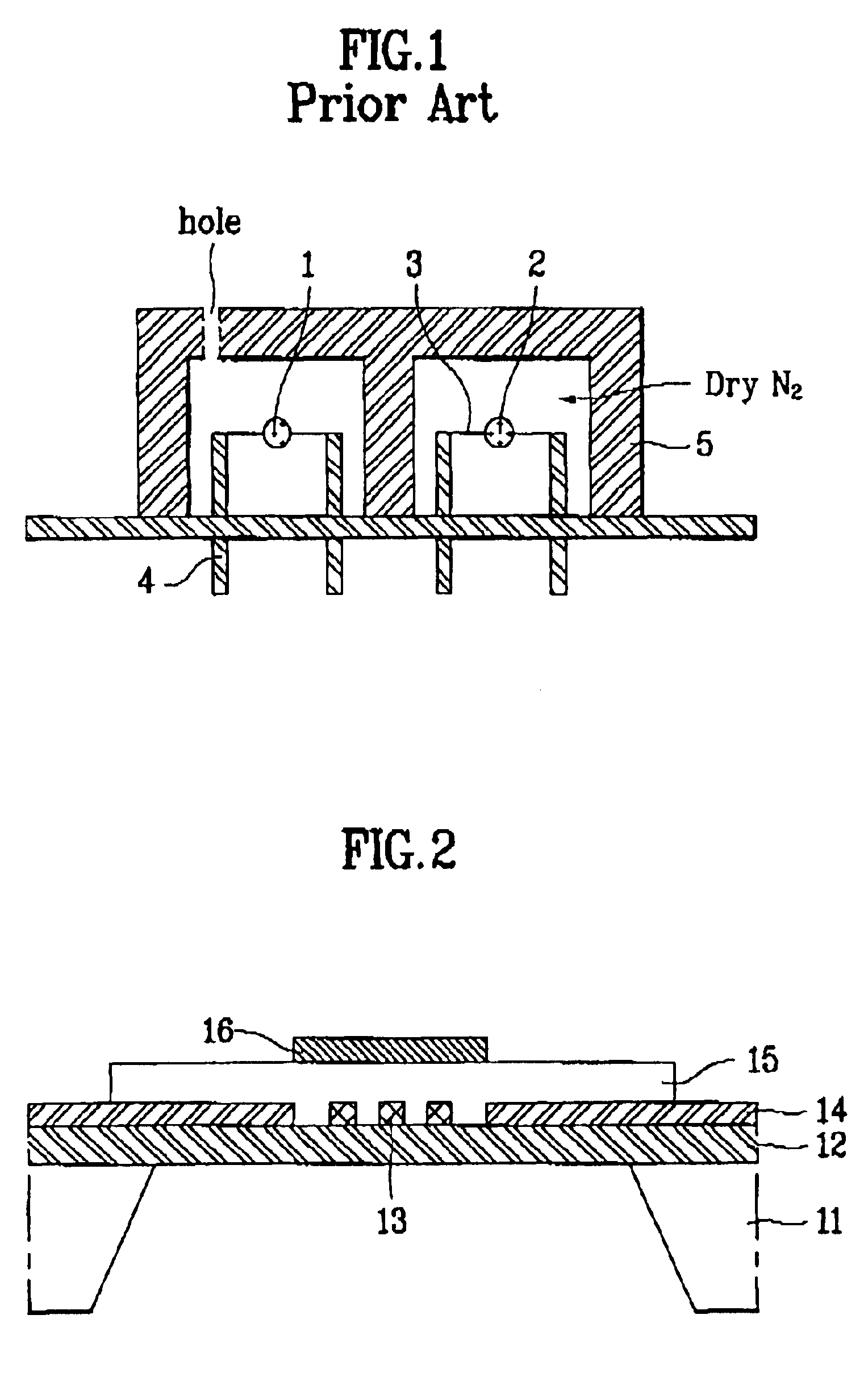
FIG. 2 is a structural sectional view showing a membrane type absolute humidity sensor according to the first embodiment of the present invention.
As shown in FIG. 2, a membrane 12 of SiO2, Si3N4, SiOxNy, or SiO2 / Si3N4 / SiO2 is formed on a silicon substrate 11. A resistor material having a temperature coefficient of resistance (TCR) is deposited on the membrane 12 and then patterned to form a resistor 13. The resistor is formed of one or more of Ti, Pt, Ni, Ni—Cr, and VO2.
Subsequently, a metal film is deposited on the resistor 13 having the TCR and then patterned to form an electrode pad 14 to be in contact with the resistor 13.
A passivation film 15 is formed on the resistor 13 to cover the resistor 13.
At this time, the passivation film 15 is formed of a material having excellent insulating characteristics, such as SiO2, Si3N4, SiOxNy, a PSG, and polyimide.
Next, a metal film such as Al or Au is deposited on the passivation film 15 and then patterned to form a thermal conductive film 1...
second embodiment
In the second embodiment of the present invention, it is intended that an absolute humidity sensor for a humidity sensing element and an absolute humidity sensor for a temperature compensating element are integrated on one chip to facilitate mass production.
FIG. 4 is a structural sectional view showing a membrane type absolute humidity sensor according to the second embodiment of the present invention.
As shown in FIG. 4, a membrane 32 of SiO2, Si3N4, SiOxNy, or SiO2 / Si3N4 / SiO2 is formed on a silicon substrate 31. A resistor material having a TCR is deposited on the membrane 32 and then patterned to form a resistor 33 for a humidity sensing element and a resistor 33b for a temperature compensating element. The resistors 33a and 33b are formed of one or more Ti, Pt, Ni, •Ni—Cr, and VO2.
Subsequently, a metal film is deposited on the resistors 33a and 33b having the TCR and then patterned to form an electrode pad 34 to be in contact with the resistors 33a and 33b.
A passivation film 35 ...
third embodiment
The third embodiment of the present invention is identical to the second embodiment in its structure.
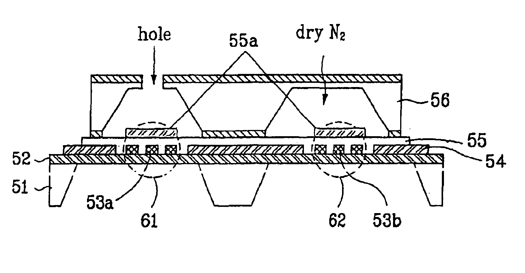
However, in the third embodiment of the present invention, external humidity is propagated into not a membrane through a stem formed at a lower portion but an insulating film through a shield case and a silicon cap which are formed at an upper portion.
FIG. 7 is a structural sectional view showing a membrane type absolute humidity sensor according to the third embodiment of the present invention, and FIGS. 8A and 8B are structural perspective views showing the membrane type absolute humidity sensor according to the third embodiment of the present invention.
As shown in FIGS. 7, 8A and 8B, a membrane 52 is formed on the silicon substrate 51. A resistor 53a for the humidity sensing element and a resistor 53b for a temperature compensating element are formed on the membrane 52. The resistors 53a and 53b are formed of one or more of Ti, Pt, Ni, Ni—Cr, and VO2.
Subsequently, an electrode pad...
PUM
Abstract
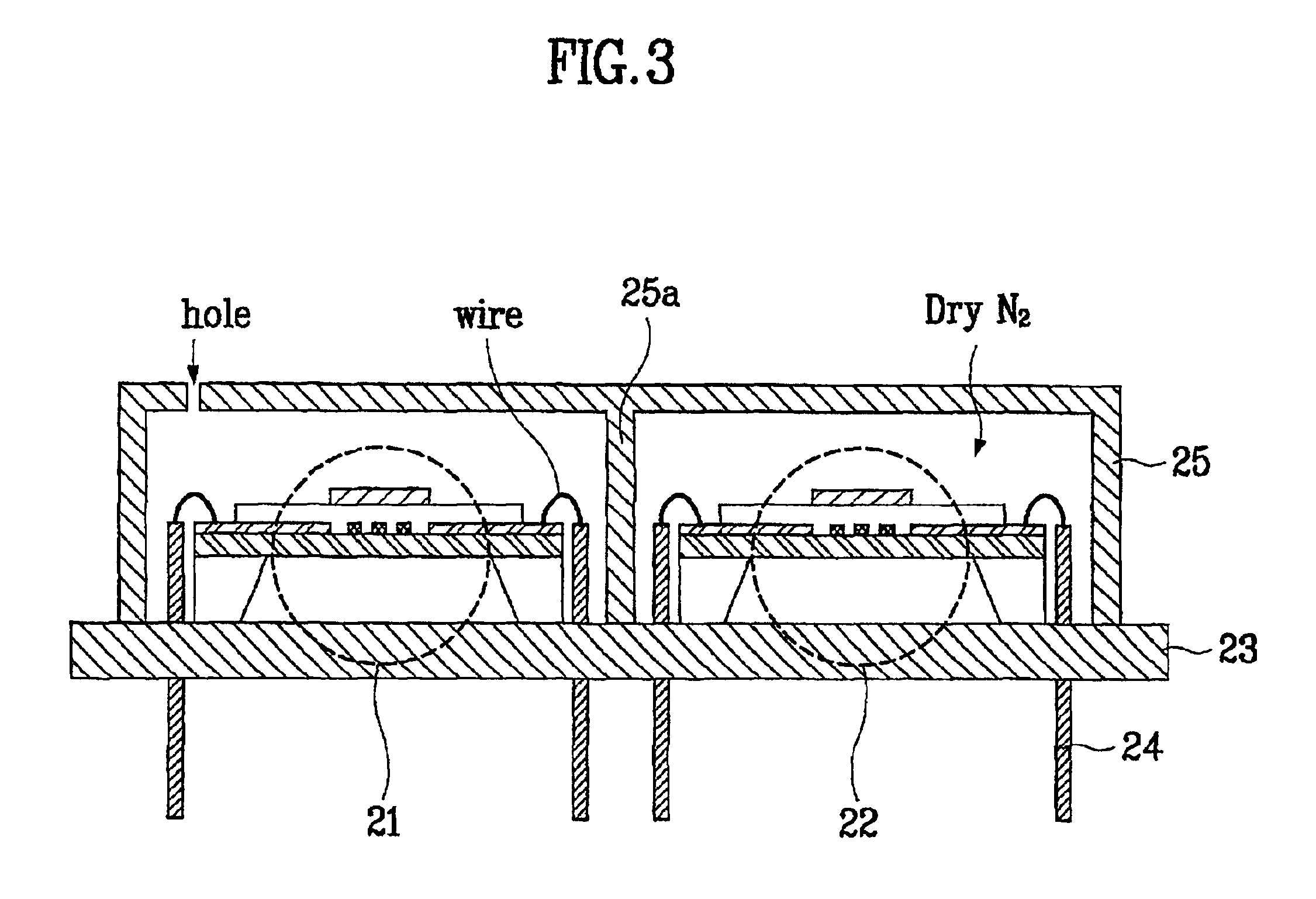
An absolute humidity sensor for a microwave oven is disclosed. The absolute humidity sensor includes a substrate having a first hole and a second hole in a predetermined region, a membrane formed on the substrate, a humidity sensing element formed on the membrane where the first hole is formed, for detecting humidity exposed to the air, having a variable resistance value depending on the detected humidity, and a temperature compensating element formed on the membrane where the second hole is formed, for compensating for the resistance value of the humidity sensing element. For package, the absolute humidity sensor further includes a stem joined with a lower portion of the substrate, having pins for electrically connecting with the outside, and a hole to pass through external humidity, a wire for electrically connecting the electrode pads of the humidity sensing element and the temperature compensating element with the pins of the stem, and a metal shield case formed on an upper portion of the stem to cover an entire surface of the stem including the humidity sensing element and the temperature compensating element.
Description
TECHNICAL FIELDThe present invention relates to an absolute humidity sensor, and more particularly, to an absolute humidity sensor for a microwave oven.BACKGROUND ARTGenerally, a humidity sensor is used for various purposes, for example, in a hygrometer, a humidity sensor for cooking of food in a microwave oven, and the like. Examples of currently used humidity sensors include a capacitance type humidity sensor, a relative humidity sensor, and an absolute humidity sensor. The capacitance type humidity sensor is based on variation of dielectric constants by hygroscopic property of an organic material such as polyimide. The relative humidity sensor is based on resistance variation of a semiconductorceramic, such as MgCr2O4. The absolute humidity sensor is based on a ceramicthermistor.Of the humidity sensors, the absolute humidity sensor based on two thermistors is widely used as a humidity sensor for cooking of food in a microwave oven.The absolute humidity sensor has an advantage i...
Claims
Application Information
Patent Timeline
Application Date:The date an application was filed.
Publication Date:The date a patent or application was officially published.
First Publication Date:The earliest publication date of a patent with the same application number.
Issue Date:Publication date of the patent grant document.
PCT Entry Date:The Entry date of PCT National Phase.
Estimated Expiry Date:The statutory expiry date of a patent right according to the Patent Law, and it is the longest term of protection that the patent right can achieve without the termination of the patent right due to other reasons(Term extension factor has been taken into account ).
Invalid Date:Actual expiry date is based on effective date or publication date of legal transaction data of invalid patent.

