

Process for heating system
- Summary
- Abstract
- Description
- Claims
- Application Information
AI Technical Summary
Benefits of technology
Problems solved by technology
Method used
Image

Examples
first embodiment
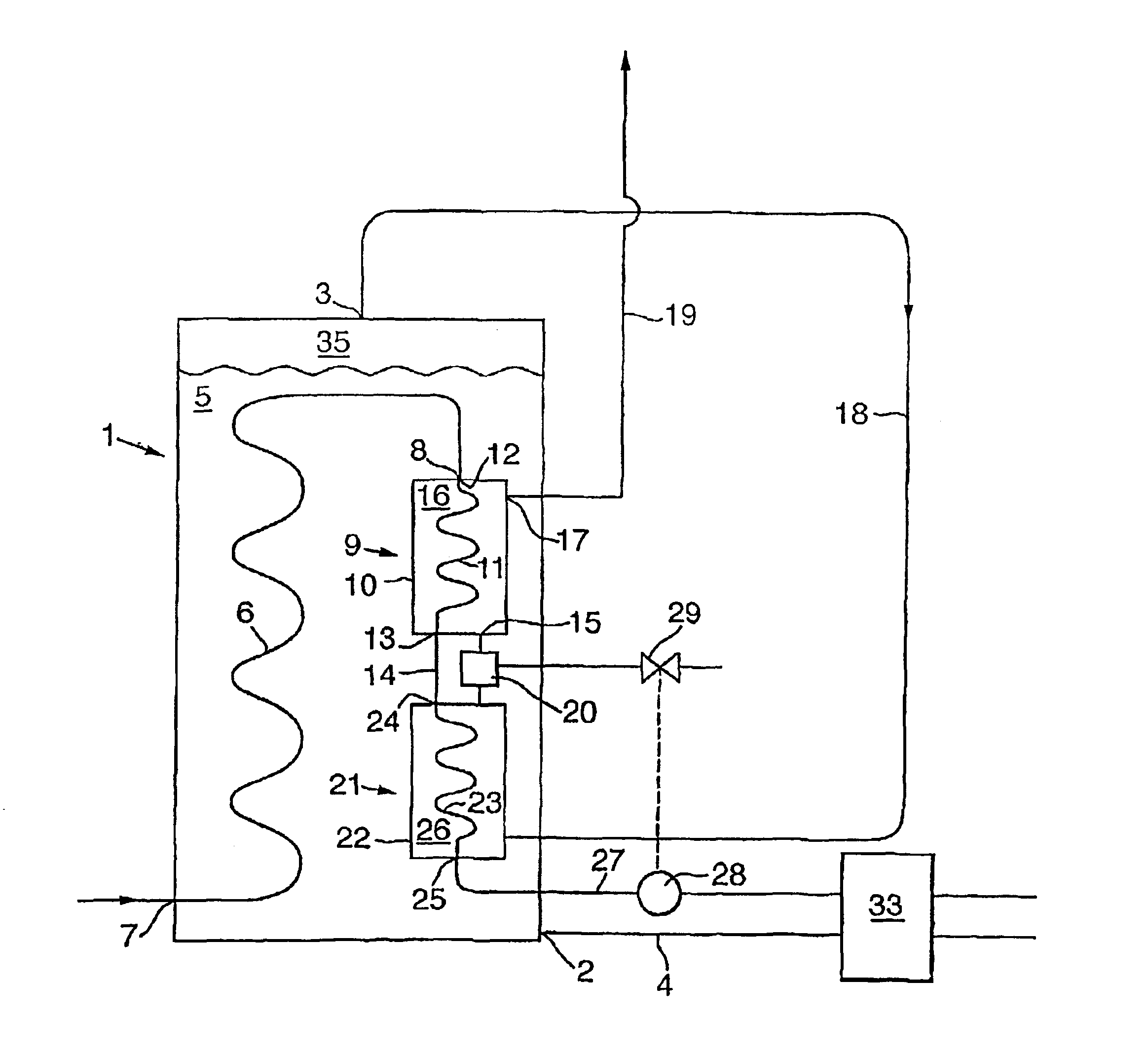
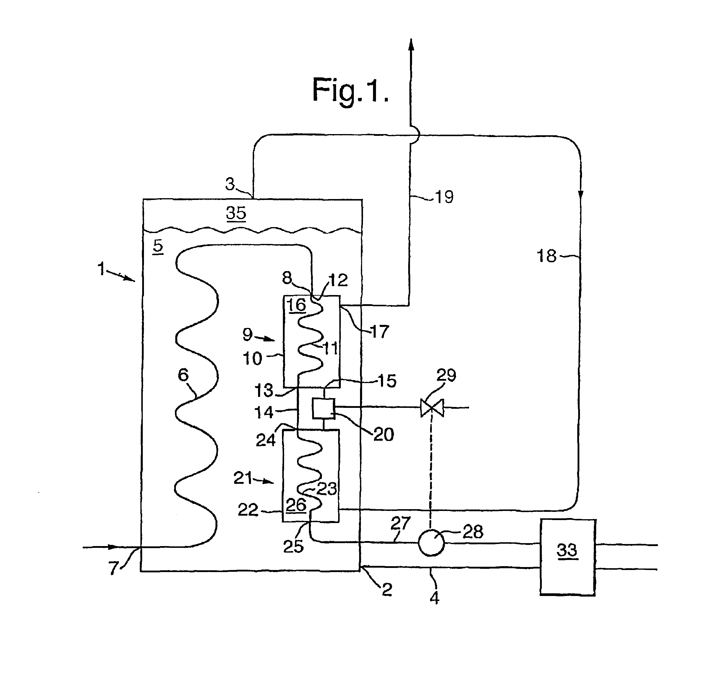
FIG. 1 shows schematically a longitudinal section of the apparatus according to the invention; and
second embodiment
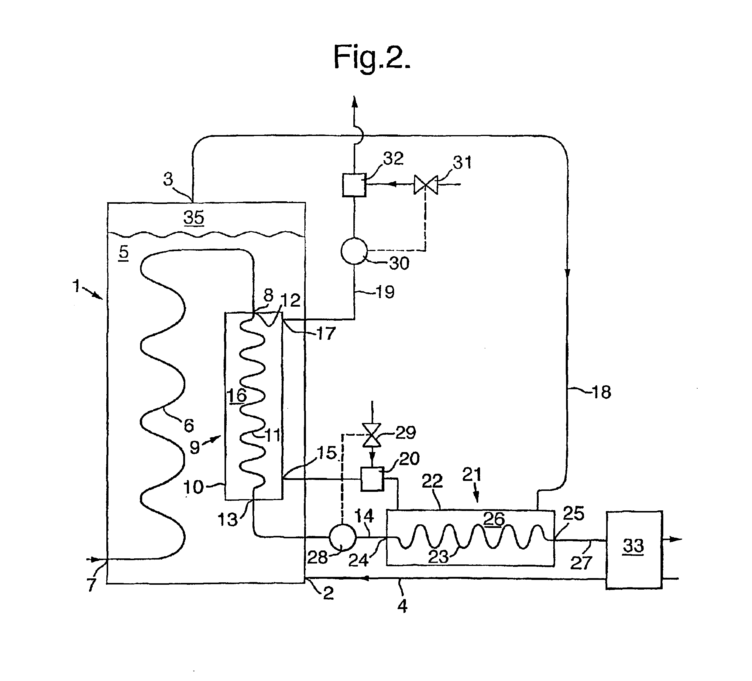
FIG. 2 shows schematically a longitudinal section of the apparatus according to the invention.
FIG. 3 shows a super heater module in more detail.
Referring now to FIGS. 1 and 2, the apparatus according to the invention comprises a primary heat exchanger vessel 1 having an inlet 2 for cooling water, which inlet 2 opens into the interior of vessel 1. The vessel 1 further comprises a compartment for cooling water 5 and a collecting space 35 for maintaining generated steam. Collecting space 35 is provided with an outlet 3 fluidly connected to a steam tube 18 for withdrawal of generated steam. The steam tube 18 may be positioned inside or outside vessel 1. A suitable embodiment of how steam tube 18 may be positioned inside vessel 1 is illustrated by FIG. 1a of EP-A-257719. Preferably a mistmat (not shown) is present between outlet 3 and steam collecting space 35 in order to avoid water droplets from entering outlet 3. During normal operation, cooling water is supplied to vessel 1 via cooli...
PUM
 Abstract
Description
Claims
Application Information