Permanent magnet rotor

a permanent magnet and rotor technology, applied in the direction of magnetic circuit rotating parts, magnetic circuit shape/form/construction, liquid fuel engines, etc., can solve the problems of increasing internal loss, increasing axial dimension, and inability to reduce axial dimension, so as to increase the overall rigidity, avoid the reduction of the cross sectional area of the permanent magnet, increase the axial dimension of the rotor

Inactive Publication Date: 2005-01-11
HONDA MOTOR CO LTD
View PDF11 Cites 24 Cited by
  • Summary
  • Abstract
  • Description
  • Claims
  • Application Information

AI Technical Summary

Benefits of technology

By thus directly connecting the permanent magnet to the power transmitting member which typically consists of a shaft, a shaft member is not required to be passed through the permanent magnet as was the case with the conventional permanent magnet rotor for the purpose of transmitting the rotational torque and increasing the overall rigidity, and the increase in the axial dimension of the rotor due to the reduction in the cross sectional area of the permanent magnet can be avoided. Also, because the sleeve surrounds the permanent magnet, the resistance to centrifugal stress resulting from a high speed rotation and repeated bending stress owing to vibrations can be improved. The reinforcement sleeve may be made of fiber reinforced plastic material which is electrically non-conductive so that eddy current loss can be avoided.
It is advantageous if the power transmitting member comprises a shaft member extending continuously from the permanent magnet, and the reinforcement sleeve overlaps a certain length of the shaft member. Because of the presence of the overlap, the part at which the power transmitting member is connected to the axial end of the permanent magnet is prevented from becoming susceptible to a mechanical failure owing to the reinforcing action of the overlapping portion of the sleeve. Experimentally, it was demonstrated that the overlap length should be selected such that L / D is 0.14 or greater where L is the overlap length, and D is an outer diameter of the permanent magnet.
According to a preferred embodiment of the present invention, the power transmitting member is connected to the axial end of the permanent magnet by brazing. In particular, it is preferable if two different brazing materials are applied to opposing ends of the permanent magnet and the power transmitting member, respectively, the brazing materials being separated by a partition wall member. The two different brazing materials can be selected so as to suit the material of the member which is to be brazed, and the partition wall member serves both as a stress buffering material to minimize stresses arising from thermal expansion at the time of brazing and as a partition wall for preventing the mixing of the two different brazing materials and thereby preventing the properties of the brazing materials from being adversely affected.

Problems solved by technology

The mechanical losses such as a bearing friction loss and a brush friction loss account for an increasingly large portion of the internal loss of a rotor for an electric generator or motor as the size of the rotor gets smaller.
However, according to the structure disclosed in Japanese patent laid open publication No. 11-234975, because the rotor is indirectly connected to the drive source consisting of a turbine via the bearing support portion, not only the axial dimension cannot be reduced but also a significant amount of eddy current loss is inevitable because the sleeve is made of metallic material even though it may not be a magnetic material.

Method used


Image

  • Permanent magnet rotor
  • Permanent magnet rotor
  • Permanent magnet rotor

Examples


Embodiment Construction

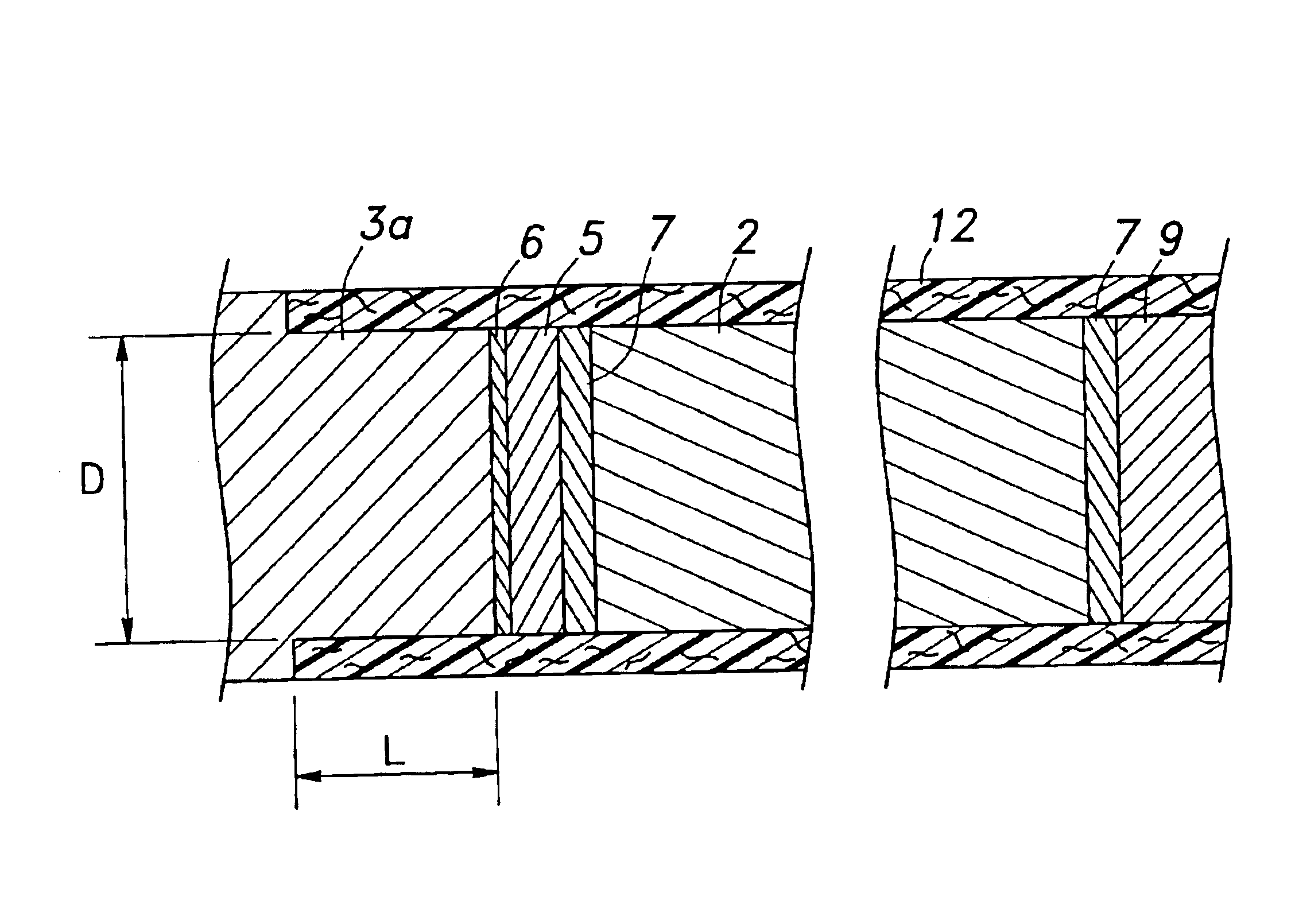
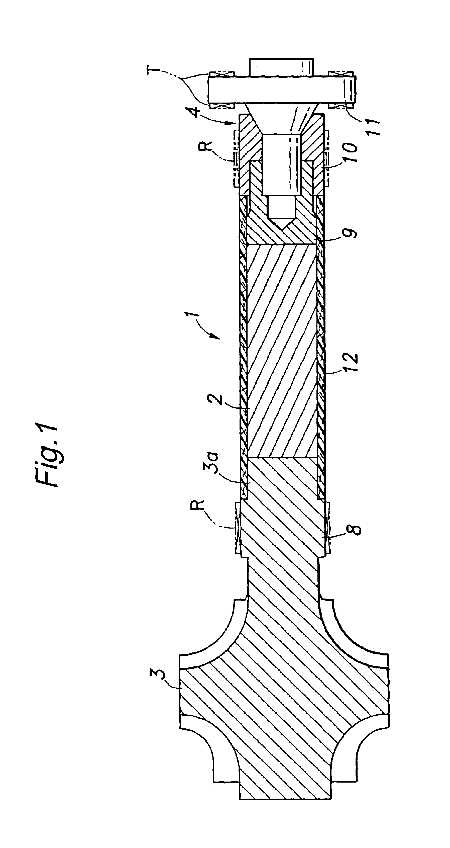
FIG. 1 shows a permanent magnet rotor having a turbine integrally formed therewith. This rotor 1 consists of a rotor for an electric generator driven by a small power plant consisting of a gas turbine engine, and comprises a cylindrical permanent magnet 2 and a shaft 3a of a turbine 3, the shaft 3a serving as a power transmitting member directly connected to an axial end surface of the permanent magnet 2. In this embodiment, the permanent magnet 2 consists of neodymium iron boron permanent magnet material (Nd15; Fe77; B8), but other permanent magnet materials such as samarium cobalt permanent magnet material may also be used to implement the present invention without substantially modifying the arrangements associated with the bonding of various parts by brazing.

A bearing support assembly 4 is connected to the other axial end surface of the permanent magnet 2. This provides a highly compact structure. The turbine 3 may be made of ceramic material such as silicon nitride and silicon ...


PUM


Abstract

In a permanent magnet rotor, a power transmitting shaft is connected to an axial end of a solid cylindrical permanent magnet, and a reinforcement sleeve is fitted on the outer circumferential surface of the permanent magnet. Thus, the shaft is not required to be passed through the permanent magnet as was the case with the conventional permanent magnet rotor for the purpose of transmitting the rotational torque and increasing the overall rigidity, and the increase in the axial dimension of the rotor due to the reduction in the cross sectional area of the permanent magnet can be avoided. Also, because the sleeve surrounds the permanent magnet, the resistance to centrifugal stress resulting from a high speed rotation and repeated bending stress owing to vibrations can be improved.

Description

TECHNICAL FIELDThe present invention relates to a rotor including a solid cylindrical permanent magnet for use in electric generators and motors.BACKGROUND OF THE INVENTIONThe mechanical losses such as a bearing friction loss and a brush friction loss account for an increasingly large portion of the internal loss of a rotor for an electric generator or motor as the size of the rotor gets smaller. Therefore, smaller rotors having a diameter of 5 mm or less often consist of permanent magnet rotors that do not required brushes. The rotor shaft for such a rotor is required to have a certain diameter that is necessary for transmitting the load or drive torque. It is therefore conceivable to use a support shaft that is passed centrally through a cylindrical permanent magnet as disclosed in Japanese patent laid open publication No. 2000-130176. This is suitable for achieving a high mechanical strength in the connection between the shaft and permanent magnet. However, according to this stru...

Claims


Application Information

Patent Timeline
Patent Type & Authority Patents(United States)
IPC IPC(8): H02K1/27H02K7/18H02K1/28
CPCF04D25/0606F04D29/053H02K7/1823H02K1/28H02K1/2726H02K1/30H02K7/14H02K15/03H02K7/025
Inventor YAMADA, KAZUYUKIMATSUNAGA, MINORU
Owner HONDA MOTOR CO LTD
Why Eureka
Try Eureka