Dynamic allocation of power supplied by a power supply and frequency agile spectral filtering of signals

a power supply and dynamic allocation technology, applied in the direction of electrical transducers, low frequency amplifiers, gain control, etc., can solve the problem that the power supply voltage/current supplied to the auxiliary circuit is inadequate for full power operation, and achieve the effect of reducing the amount of power available, reducing power supply cost, and large low frequency bass output sound level

Inactive Publication Date: 2005-01-11
INTERDIGITAL MADISON PATENT HLDG
View PDF11 Cites 3 Cited by
  • Summary
  • Abstract
  • Description
  • Claims
  • Application Information

AI Technical Summary

Benefits of technology

According to aspects of the present invention, the conflict is resolved by the dynamic allocation of power from the power supply between the main power amplifiers and the sub-woofer power amplifier. When a control circuit detects an audio signal above a predetermined threshold in the sub-woofer frequency range, a switch is operated which reduces the amount of power available from the main power supply to the auxiliary sub-woofer power amplifier thus switching the auxiliary power amplifier from a fully operational mode to a lower power mode, while still providing a large low frequency bass output sound level but at a reduced power supply cost.
In a preferred embodiment, the first impedance state corresponds to a low resistance, the supply voltage / current applied to the auxiliary power amplifier is the full operating voltage and the second impedance state corresponds to a relatively higher resistance state so that the maximum power output from the auxiliary circuit is reduced.
The variable-impedance in the exemplary embodiment comprises a fast acting relay having its operating coil connected to the control circuit and a switch contact connected in parallel with an impedance such as a power resistor. Opening of the switch contact inserts the impedance in series with the power supply, reducing the power supply voltage / current provided to the auxiliary amplifier to a lower level. Conversely, closing the switch contact short-circuits the impedance, putting a zero or negligible impedance into the power supply path, thus raising the common power supply voltage available for full power output of the auxiliary amplifier. For momentary peak power levels shorter in duration than the reaction time of the relay, the power supply capacitors should be sufficiently large to maintain power supply voltages / currents.

Problems solved by technology

In the first impedance state, the power supply voltage / current supplied to the auxiliary circuit permits its full power operation, and in the second impedance state, the power supply voltage / current supplied to the auxiliary circuit is inadequate for full power operation.

Method used


Image

  • Dynamic allocation of power supplied by a power supply and frequency agile spectral filtering of signals
  • Dynamic allocation of power supplied by a power supply and frequency agile spectral filtering of signals
  • Dynamic allocation of power supplied by a power supply and frequency agile spectral filtering of signals

Examples


Embodiment Construction

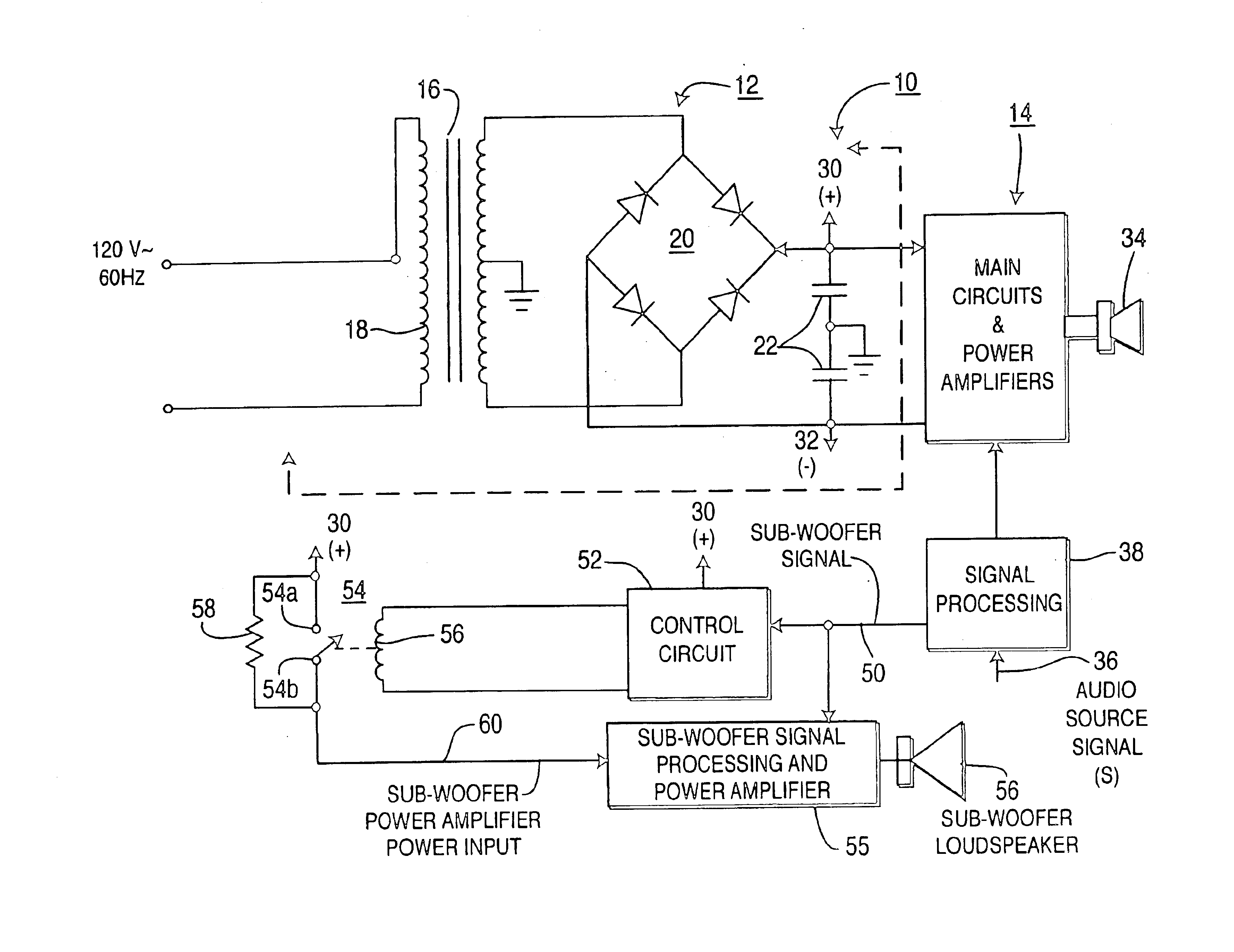
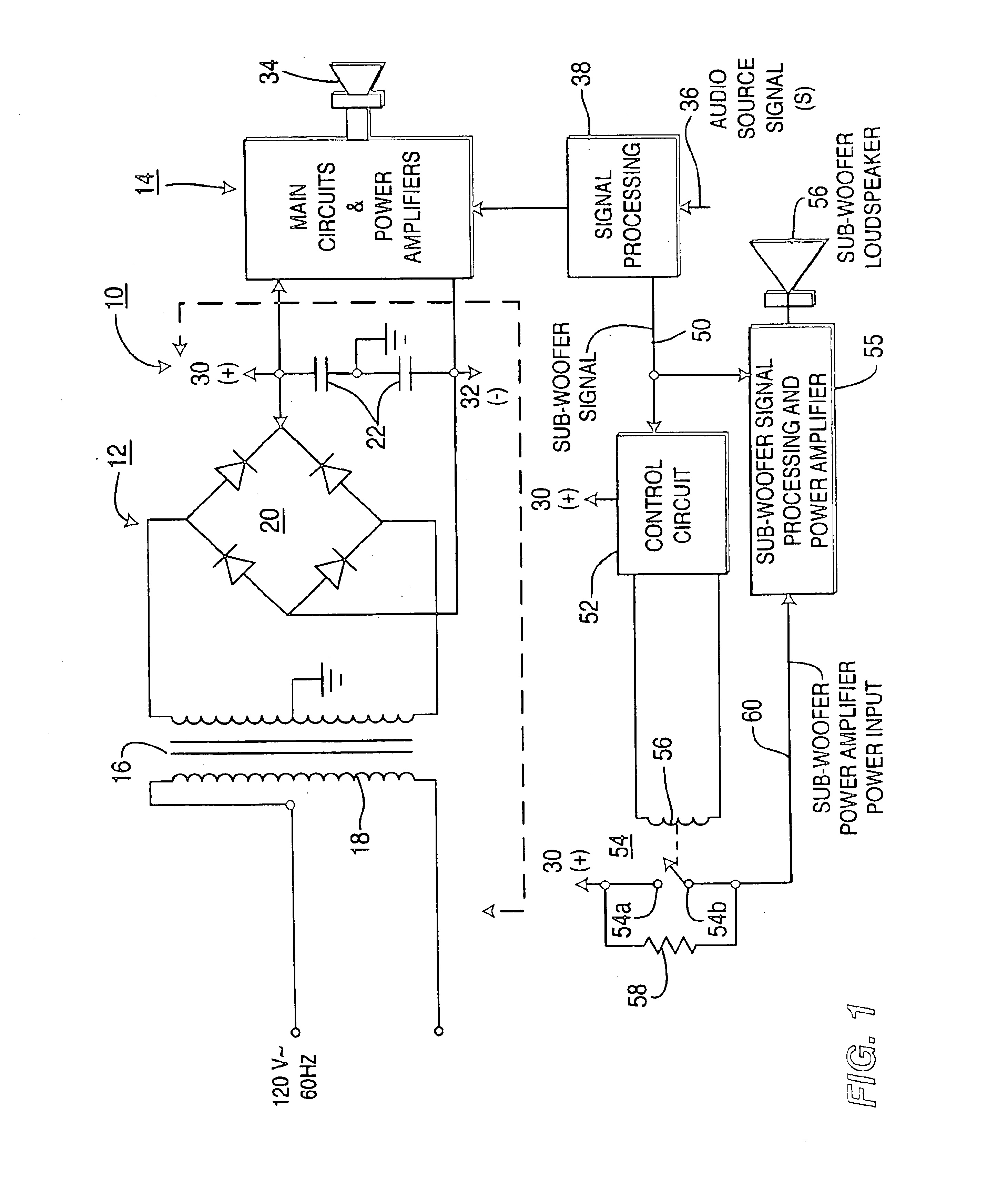
FIG. 1 shows an amplifier system 10 which includes a power supply 12 and amplifier circuits including power amplifiers 14. Power supply 12 shows a power transformer 16 having a primary winding 18 connectable to an AC power line, a secondary winding 20 connected to a full wave diode bridge 21, and power supply filter capacitors 22 for providing DC power of appropriate voltage and current to amplifier circuits 14 at nodes 30 (+) and 32 (−). There are many possible configurations for power supply 12, for example, the power supply 12 is balanced with a center-tapped ground. The power supply shown is merely exemplary and forms no part of the present invention. In this regard, it should be noted that in a television receiver having a CRT video display, some audio power amplifiers may be powered from the flyback circuit.

Main circuits and power amplifiers 14 includes audio circuitry other than sub-woofer signal processing and loudspeaker drive, and provide power output to a plurality of lou...


PUM


Abstract

The power voltage supply for a power amplifier is switched between an operational full power mode and a reduced power mode by the switching of a dual state impedance device connected in series between the power amplifier and the power supply. A control circuit detects the level of a signal to be amplified by that amplifier and switches the impedance states thus reducing the power output capability of the power amplifier and placing the power amplifier into a reduced power mode. In one embodiment, the signal is produced by spectrally filtering with a low pass filter, with the cross-over frequency being adjustable. Additionally, the gain of the amplifier can be reduced for high level signals.

Description

TECHNICAL FIELDThe present invention relates to power supply circuit arrangements for electrical equipment, and more particularly, is applicable to power supply circuit arrangements which allow equipment to be switched between an operational mode, and a reduced power or standby mode.BACKGROUNDSome high fidelity audio systems, e.g., so-called “surround sound” systems using Dolby Pro-logic™ or Dolby Digital™ include power amplifiers for each of the sound signals provided by such Dolby™ systems, e.g., left, right, center, left rear, right rear. In a home audio system, these audio power amplifiers would be powered by a common main power supply.Normally, for a comfortable listening level, one needs to boost the signal response in the low frequency bass range. The Dolby™ systems provide a sub-woofer signal which is outputted to a sub-woofer system, which can be a separate active unit which includes a preamplifier / buffer, a high power audio power amplifier, and a large diameter loudspeaker...

Claims


Application Information

Patent Timeline
Patent Type & Authority Patents(United States)
IPC IPC(8): H03F1/02H03F3/181H03F3/20H04S5/02H04R3/00
CPCH03F1/0211H03F3/181H03F2200/504H03F2200/03H02M7/00
Inventor CALDWELL, ROCKY
Owner INTERDIGITAL MADISON PATENT HLDG
Why Eureka
Try Eureka