
Compact ductless cooling with heat exchangers

a technology of heat exchangers and ductless cooling, which is applied in the direction of lighting and heating apparatus, active medium materials, semiconductor/solid-state device details, etc., can solve the problems of inability to exhaust heated air into the facility, insufficient heat exchangers for heating components, waste heat generation of lasers and other electronic equipment during operation, etc., to achieve convenient access to components, save valuable floor space and costs, and avoid complicated ducting

Inactive Publication Date: 2005-01-18
CYMER INC
View PDF20 Cites 7 Cited by
  • Summary
  • Abstract
  • Description
  • Claims
  • Application Information

AI Technical Summary

Benefits of technology

The present invention is about a way to cool electronic equipment using a recirculating air flow loop that is confined within the equipment enclosure. The air flow loop removes waste heat from the equipment through a heat exchanger, which transfers the heat to a flowing liquid. The cooled air flow loop is redirected and impinges on the heat-generating components again, cooling them. The invention is particularly useful for cooling laser equipment, which can be cooled using a single heat exchanger or multiple heat exchangers without complicated ducting and without exhausting heated air into a controlled manufacturing environment. The simplified cooling configuration conserves floor space and costs, and facilitates access to components for periodic maintenance. The invention also prevents short circuits and shock hazards from water leakage onto high voltage devices.

Problems solved by technology

Lasers and other electronic equipment generate waste heat during operation.
In some controlled environments, e.g. clean room facilities for microelectronic circuit processing, it is not acceptable to exhaust heated air into the facility.
At higher power levels, a separate exhaust system for heated air may also be inadequate to prevent overheating of components.
However, if the components to be cooled involve multiple ventilation grilles and openings, it is difficult to design a duct that will seal around every opening, especially with multiple components.
Additionally, water cooling adjacent to high voltage equipment often carries a risk of water leakage onto high voltage components, leading to short circuit, catastrophic equipment breakdown, and electric shock hazards.
If these components are not cooled, temperature will build up in the interior of enclosure 102, leading to performance degradation or component failure.
Additionally, such manufacturing equipment typically requires periodic maintenance or component replacement.
In accordance with the conventional art, this often requires a design compromise between compactness and access.
Complex and bulky cooling ducts consume valuable manufacturing floor space and often interfere with access to equipment components.

Method used


Image

  • Compact ductless cooling with heat exchangers
  • Compact ductless cooling with heat exchangers
  • Compact ductless cooling with heat exchangers

Examples


Embodiment Construction

The following is a detailed description of illustrative embodiments of the present invention. As these embodiments of the present invention are described with reference to the aforementioned drawings, various modifications or adaptations of the methods and or specific structures described may become apparent to those skilled in the art. All such modifications, adaptations, or variations that rely upon the teachings of the present invention, and through which these teachings have advanced the art, are considered to be within the spirit and scope of the present invention. Hence, these descriptions and drawings are not to be considered in a limiting sense as it is understood that the present invention is in no way limited to the embodiments illustrated.

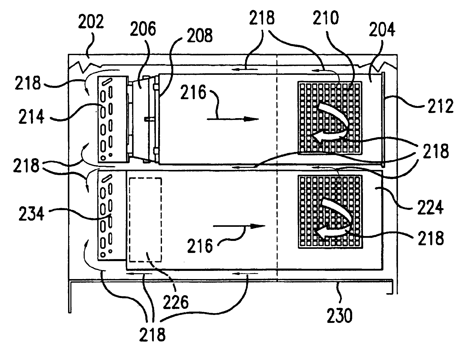
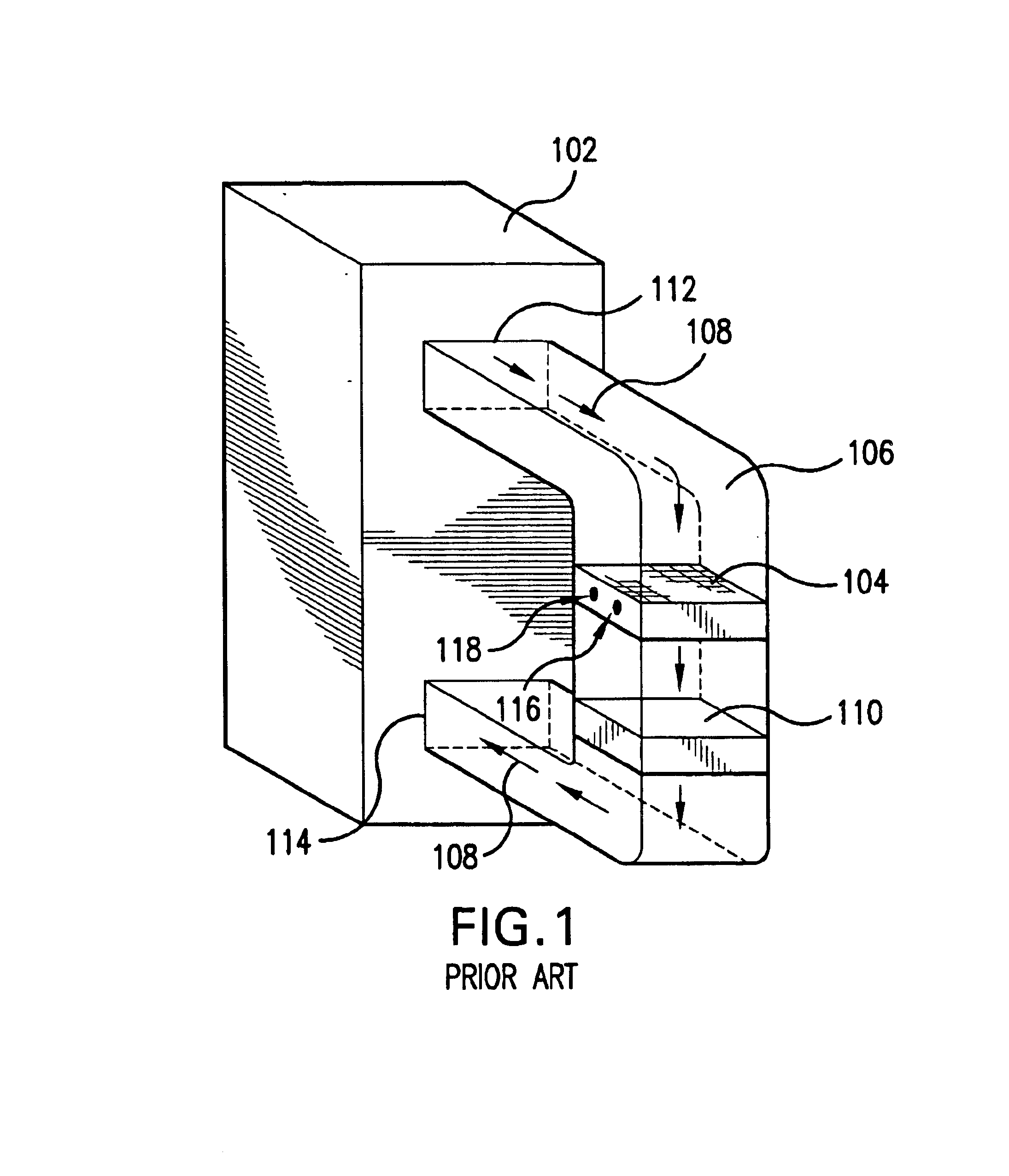
FIG. 2 is a schematic view of an electronic enclosure 202 internally containing at least one electronic housing 204. Housing 204 contains internal heat-generating components (not shown). Typically, at least one conventional blower 206 is...


PUM


Abstract

Heat is removed from an equipment enclosure using a recirculating air flow loop that is confined entirely within the enclosure. A segment of the air flow loop is directed onto heat-generating components, contained within housings mounted inside the enclosure. A segment of the air flow loop carries heated air to a heat exchanger, which transfers heat to flowing liquid. A portion of the air flow loop traverses through the ductless air volume confined between the housings and inner walls of the enclosure. Blowers to drive the air flow are typically mounted within or on a housing. Heat exchangers are also typically mounted on a housing. Embodiments of the present invention enable a single heat exchanger or multiple heat exchangers to cool multiple electronic components without complicated ducting and without exhausting heated air into a controlled manufacturing environment, e.g. a clean room.

Description

FIELD OF THE INVENTIONThe present invention relates to heat exchangers and methods of heat transfer, and particularly relates to ductless cooling with heat exchangers in conjunction with lasers and electrical power equipment.BACKGROUNDLasers and other electronic equipment generate waste heat during operation. At higher power levels typically required for industrial operation, removal of this waste heat is important to avoid temperature increases that could otherwise degrade the performance of the electronic equipment and related apparatus. A conventional method for disposing of waste heat is to blow ambient air over the heat-generating components and to exhaust the heated air through a room air conditioning system. In some controlled environments, e.g. clean room facilities for microelectronic circuit processing, it is not acceptable to exhaust heated air into the facility. At higher power levels, a separate exhaust system for heated air may also be inadequate to prevent overheating...

Claims


Application Information

Patent Timeline
Patent Type & Authority Patents(United States)
IPC IPC(8): H01S3/14H01S3/225H01S3/04
CPCH01S3/225H01S3/0404
Inventor THOMPSON, PAUL S.
Owner CYMER INC
Learn More