Self-adjusting clutch release bearing

Inactive Publication Date: 2005-01-18
SCHAEFFLER TECH AG & CO KG
View PDF18 Cites 14 Cited by
  • Summary
  • Abstract
  • Description
  • Claims
  • Application Information

AI Technical Summary

Benefits of technology

The present invention resolves prior art problems by providing a sliding element made of a thermoplastic material. This material has a high thermal shock stress and improved crack resistance compared to conventionally used materials. Thermoplastic material is also low in friction and sufficiently wear-resistant as a result of its hardness and strength. Thus, the service life is prolonged and matches the service life of the internal combustion engine.
According to another feature of the present invention, the sliding element may be made of highly heat-resistant polyamides or other highly heat-resistant thermoplastic material such as polyaryletherketone (PAEK). These materials may be admixed with additives to vary the material property. Additives of the type involved here have a positive influence on friction, wear and strength to optimize the thermoplastic material for use as material for the sliding element. In addition, thermoplastic material admixed with additives is easy to process and inexpensive. Another, currently preferred thermoplastic material for the sliding element involves PA 46 CF 30/PTFE 5/H. The combination of the thermoplastic material with carbon fibers as additive and polytetrafluoroethylene as solid lubricant is best suited to minimize friction and wear and thus to prolong the service life.
As a consequence of the low crack risk of the thermoplastics, these materials can easily be combined with the steel material of the adjustment ring or bearing ring. Suitably, the sliding element has a thickness in the range of 0.5 mm to 6 mm.
According to another feature of the present invention, the sliding ring may be connected to the adjustment ring or to the respective bearing ring. To ensure clarity, the following description uses the term “component” to refer to the part that is connected to the sliding element, i.e. either to the adjustment ring or the bear

Problems solved by technology

The axial misalignment, caused by the disk spring, and axial misalignment as a consequence of manufacturing tolerances between force-transmitting shafts of the internal combustion engine and the gearbox, whereby the clutch release bearing is disposed between the internal combustion engine and t

Method used


Image

  • Self-adjusting clutch release bearing
  • Self-adjusting clutch release bearing
  • Self-adjusting clutch release bearing

Examples


Example

Throughout all the Figures, same or corresponding elements are generally indicated by same reference numerals. These depicted embodiments are to be understood as illustrative of the invention and not as limiting in any way. It should also be understood that the drawings are not necessarily to scale and that the embodiments are sometimes illustrated by graphic symbols, phantom lines, diagrammatic representations and fragmentary views. In certain instances, details which are not necessary for an understanding of the present invention or which render other details difficult to perceive may have been omitted.

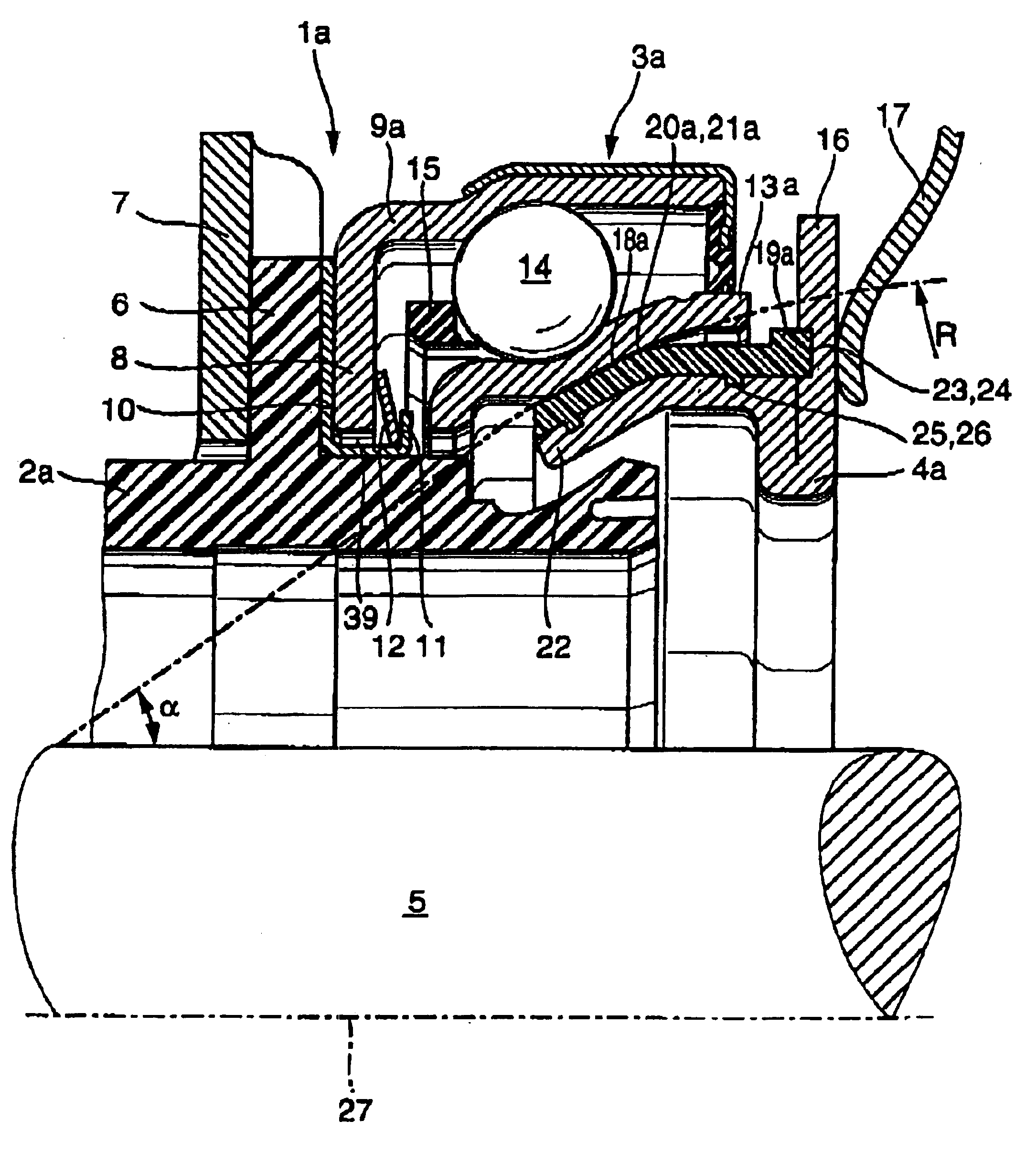
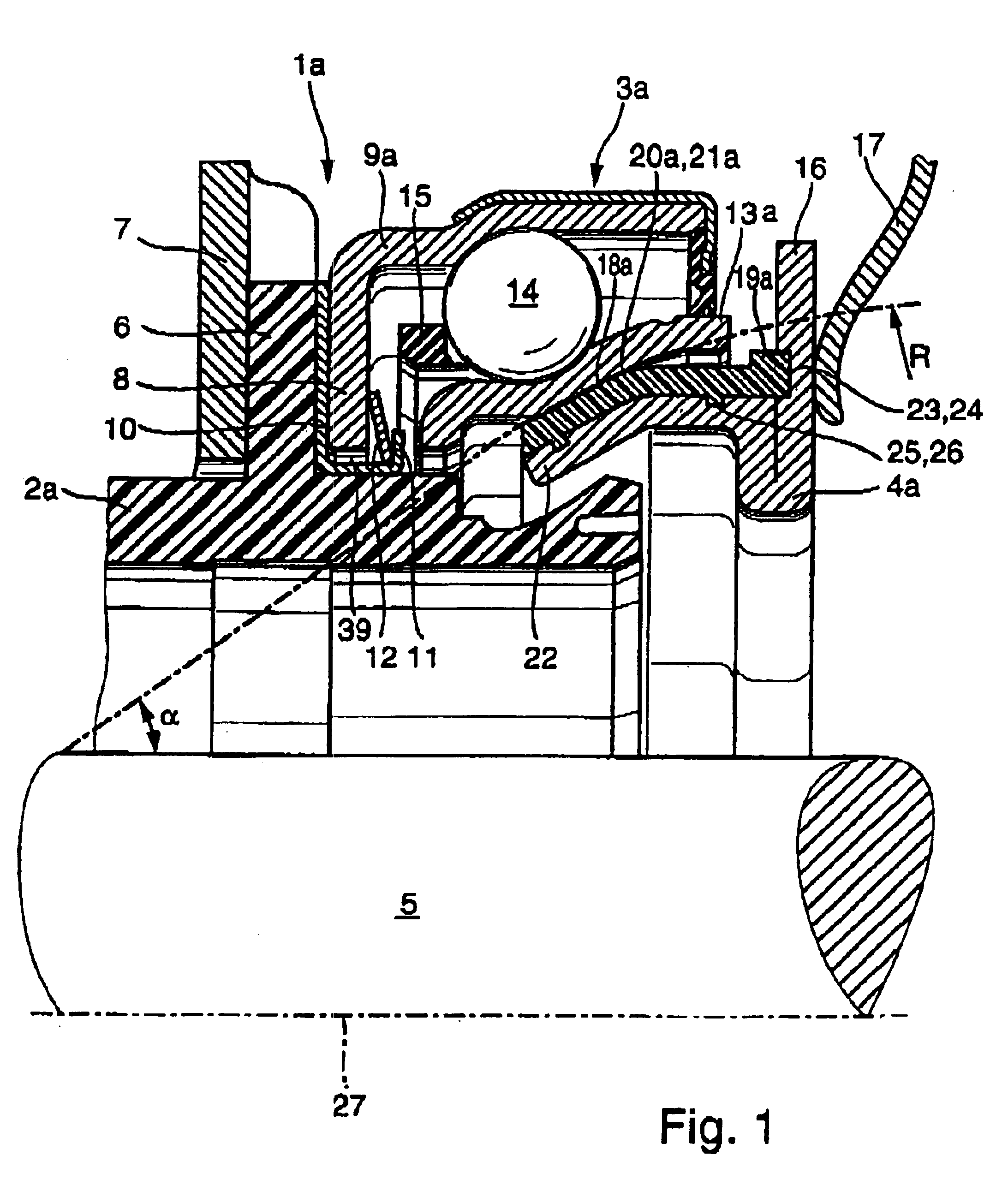
Turning now to the drawing, and in particular to FIG. 1, there is shown a half-section of a release mechanism, generally designated by reference numeral 1a and defined by a symmetry axis 27. The release mechanism 1a includes a casing 2a which is guided on a guide sleeve positioned in concentric surrounding relationship to a driveshaft 5 which connects an internal combustion engine t...


PUM


Abstract

A self-adjusting release bearing in the form of a tapered rolling bearing for a separating clutch disposed between an internal combustion engine and a gearbox of a motor vehicle, includes a non-rotating first bearing ring, a revolving second bearing ring, and a plurality of rolling elements guided between the first and second bearing rings. Supported upon a calotte-shaped section of one of the first and second bearing rings in a contact zone is an adjustment ring having a complementary calotte-shaped section to thereby allow pivoting of the release bearing, whereby a sliding element made of thermoplastic material is disposed in the contact zone.

Description

BACKGROUND OF THE INVENTIONThe present invention relates, in general, to a clutch release bearing for a motor vehicle.A clutch release bearing is typically intended for actuation of a clutch mechanism, e.g. separating clutch, disposed between the internal combustion engine and a gearbox, and is configured as a tapered roller bearing which includes a non-rotatable bearing ring, a revolving bearing ring, and rolling members, received in a cage and guided between the bearing rings. Operatively connected to one of the bearing rings is an adjustment ring, which establishes a connection between a disk spring of the clutch mechanism and the clutch release bearing. The adjustment ring is configured to allow a relative movement of the adjustment ring and the associated one of the bearing rings so as to implement a self-adjustment or self-alignment of the release bearing.Such a release bearing is able to compensate shocks generated by axial misalignment with the disk spring that is connected ...

Claims


Application Information

Patent Timeline
IPC IPC(8): F16C23/00F16D23/14F16D23/00F16C23/08F16C33/30
CPCF16C23/084F16D23/144F16C2361/43F16C19/163F16D23/14
Inventor DITTMER, STEFFENWINKELMANN, LUDWIGKLOPFER, BERNHARD
Owner SCHAEFFLER TECH AG & CO KG
Why Eureka
Try Eureka