Method and apparatus of a fast two-loop automatic gain control circuit

a gain control and two-loop technology, applied in electrical equipment, digital transmission, multiple carrier systems, etc., can solve problems such as ineffective data communication, increased system instability, and increased conflict between these last two design parameters, so as to reduce the size and cost of hardwar

Inactive Publication Date: 2005-01-18
GOOGLE LLC
View PDF3 Cites 84 Cited by
  • Summary
  • Abstract
  • Description
  • Claims
  • Application Information

AI Technical Summary

Benefits of technology

The present invention provides a fast AGC circuit through the use of a fine-gain feedback loop and a coarse-gain feedback loop to provide both the speed and control needed for high-speed digital communication systems. In addition, by utilizing circuits already present in a typical receiver and avoiding any redundant introduction of similar circuitry in each individual control loop, the inventive AGC circuit reduces both the size and cost of the hardware when compared to earlier systems.

Problems solved by technology

The evolution of wireless communications to very high data rates with packet transmissions over the air has imposed constraints on the receiving system radio-frequency (RF) stages as well as on the operation of the analog-to-digital converters used therein.
Some conditions that can contribute to this wide operating range include signal attenuation caused by hills or buildings and power control failure occurring when a mobile transmitter is in close proximity to a base station receiver.
As the control system parameters are configured and set to improve the system's response time, system instability, such as overshoot conditions, are likely to increase.
In high data rate digital communications, and especially in packet switched systems, the conflict between these last two design parameters becomes increasingly important.
Because the start of each packet introduces a large signal variation and the periods of symbols within a packet are so short, a conventional AGC is not able to ensure timely amplification control for the received signal and, therefore, will prove ineffective at providing reliable data communications.

Method used


Image

  • Method and apparatus of a fast two-loop automatic gain control circuit
  • Method and apparatus of a fast two-loop automatic gain control circuit
  • Method and apparatus of a fast two-loop automatic gain control circuit

Examples


Embodiment Construction

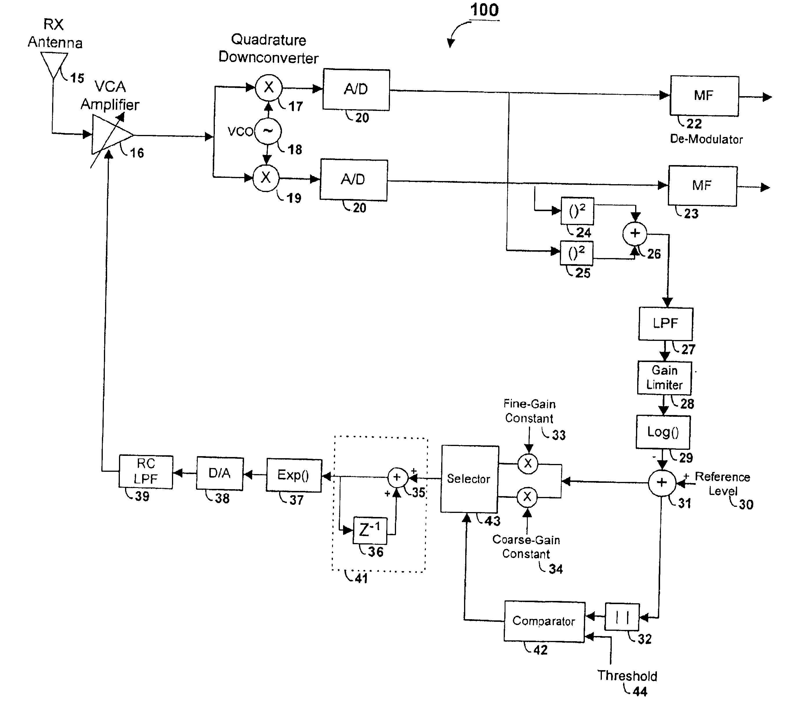
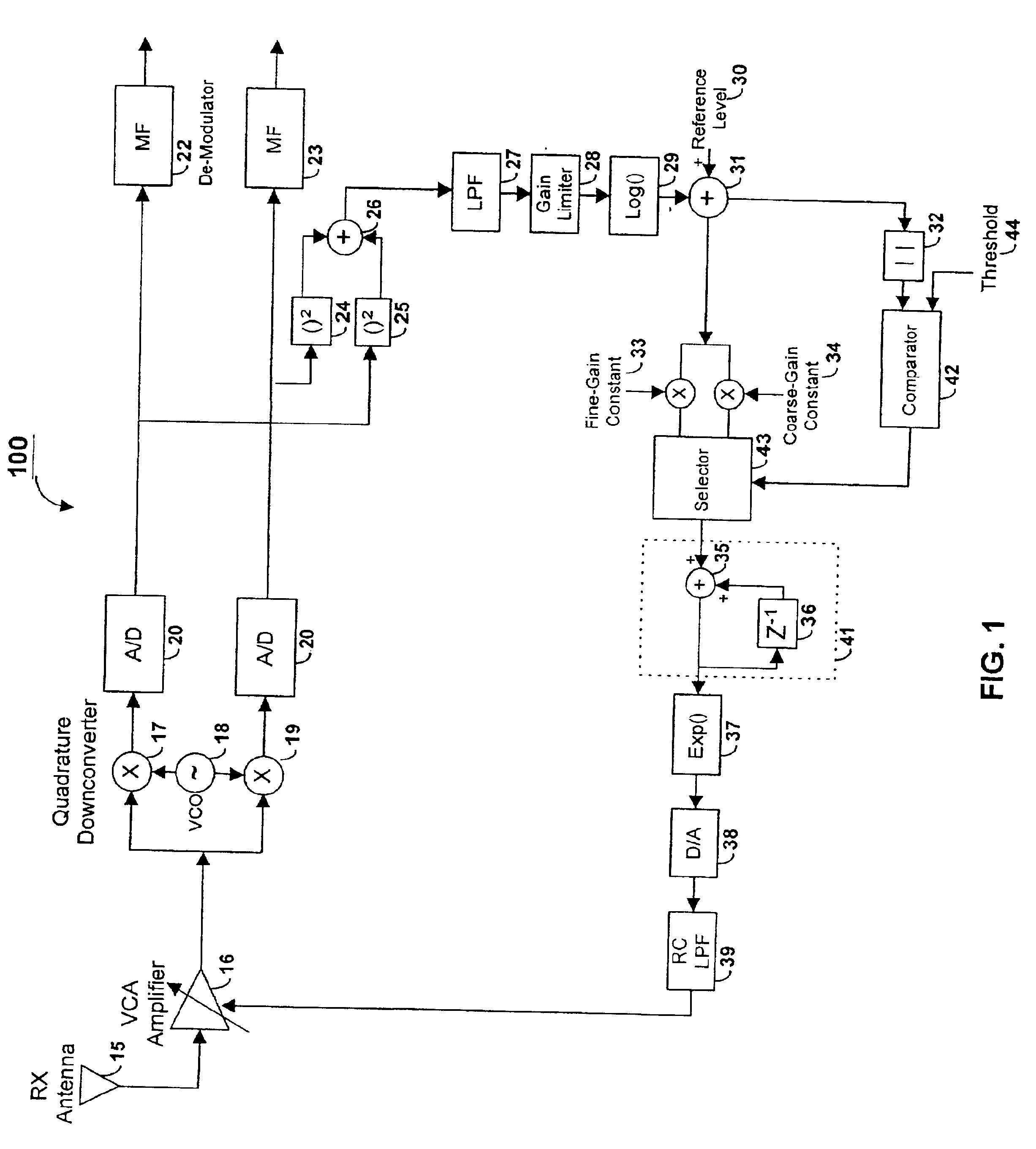
FIG. 1 illustrates an automatic gain control circuit 100 according to certain embodiments of the present invention for use with a receiver system or a transceiver system. While the AGC circuit 100 is described within the exemplary environment of a direct sequence spread-spectrum receiver, the present AGC circuit also has application to other types of receiver systems that would similarly benefit from fast, dynamic control of the amplification of the received signal. The present invention has benefit within a receiver of both base stations and mobile stations.

Previous efforts undertaken have investigated fast response AGC circuitry for high-speed communications systems. These previous efforts, however, involved generating coarse signal strength information from the analog received signal and producing finer control information from separate analog-to-digital converted signal inputs. The coarse and fine information were then used in combination with a look-up table to generate gain co...


PUM


Abstract

In a burst-mode, high-speed spread-spectrum communications system, faster convergence of a receiver's automatic gain control (AGC) circuit reduces the time required to bring a received signal within the operating range of an operation amplifier and other radio-frequency and digital sections of the receiving system. A gain control circuit includes a coarse-gain feedback loop and a fine-gain feedback loop to improve convergence speed and at the same time maintain the stability of the AGC circuit. The coarse-gain feedback loop quickly brings the received signal, using a large gain signal, to the desired operating range. The fine-gain feedback loop uses a smaller gain signal to gradually smooth the received signal to avoid saturation on the A/D converters.

Description

FIELD OF THE INVENTIONThis invention is related to digital communications systems, and more particularly to a programmable, fast response and fast convergence automatic gain control (AGC) circuit for packet communication systems.BACKGROUNDMobile communication is becoming increasingly popular and the recent advances in digital processing have allowed a rapid migration of mobile services from analog communications to digital communications. Increasingly, development efforts are focusing on techniques for high-capacity communication of digital information over wireless links, and much of this wireless development work incorporates spread-spectrum communications technology.Spread-spectrum is a method of modulation that spreads a data signal for transmission over a bandwidth, which substantially exceeds the data transfer rate. Direct sequence spread-spectrum involves modulating a data signal onto a pseudo-random chip sequence. The chip sequence is the spreading code sequence for spreadin...

Claims


Application Information

Patent Timeline
Patent Type & Authority Patents(United States)
IPC IPC(8): H03G3/30H04L27/38H04L27/00H04B1/707
CPCH03G3/3052H04L27/3809H04L2027/0067H04B1/7117
Inventor LI, DONYANG, GANG
Owner GOOGLE LLC
Why Eureka
Try Eureka