Apparatus and methods for removing optical abberations during an optical inspection

a technology of optical abberation and optical inspection, which is applied in the direction of optically investigating flaws/contamination, structural/machine measurement, instruments, etc., can solve the problems of false defects, the fabrication process itself introduces discrepancies between the target structure and the reference image, and introduces discrepancies between the reference and target image, etc., to achieve the effect of eliminating aberrations

Inactive Publication Date: 2005-01-18
KLA TENCOR TECH CORP
View PDF5 Cites 38 Cited by
  • Summary
  • Abstract
  • Description
  • Claims
  • Application Information

AI Technical Summary

Benefits of technology

Accordingly, the present invention provides mechanisms for altering the phase and / or amplitude of an optical beam within an inspection system using one or more spatial light modulator(s) (SLMs). In one embodiment, an apparatus for optically inspecting a sample with an optical beam is disclosed. The apparatus includes a beam generator for directing an incident optical beam onto the sample whereby at least a first portion of the incident optical beam is directed from the sample as an output beam and a detector positioned to receive at least a portion of the output beam. The detector is also operable to generate an output signal based on the output beam. The apparatus further includes one or more imaging optics for directing the output beam to the detector and a programmable spatial light modulator (SLM) positioned within an optical path of the incident or output beam. The SLM is configurable to adjust a phase and / or amplitude profile of the incident beam or the output beam. The apparatus also has a control system operable to configure the SLM to alter the phase and / or amplitude profile of the incident beam or the output beam. For example, the SLM may be configured to alter the illumination profile of the incident beam to achieve different inspection modes. In another example, the SLM may be configured to alter the phase and / or amplitude profile of the output beam so as to substantially eliminate aberrations produced by the imaging optics. In other embodiments, the apparatus may include two or more SLM's which are configurable to alter the phase and / or amplitude profile of both the incident beam and the output beam.

Problems solved by technology

Unfortunately, these inspection mechanisms frequently result in false defects when the target images significantly differ from their corresponding reference images and these differences are not caused by “real” defects.
When the target structures are fabricated from a set of original design patterns which are also used as the reference images, the fabrication process itself introduces discrepancies between the target structures and the reference images.
Imaging of the target structures during inspection also introduces discrepancies between the reference and target images.
This iterative process is typically complex and time consuming.
Although this iterative process may result in a reference image that resembles the target image, it may also unintentionally add a feature to the reference image that corresponds to a “real” defect in the target image so that capture of “real” defects on the target image is hindered.
Since a defect is defined as a difference between the reference image and the target image and the reference image has been altered to resemble the target image, this technique may cause “real” defects on the target to be cancelled by simulated portions of the reference image so that the “real” defect are not found.

Method used


Image

  • Apparatus and methods for removing optical abberations during an optical inspection
  • Apparatus and methods for removing optical abberations during an optical inspection
  • Apparatus and methods for removing optical abberations during an optical inspection

Examples


first embodiment

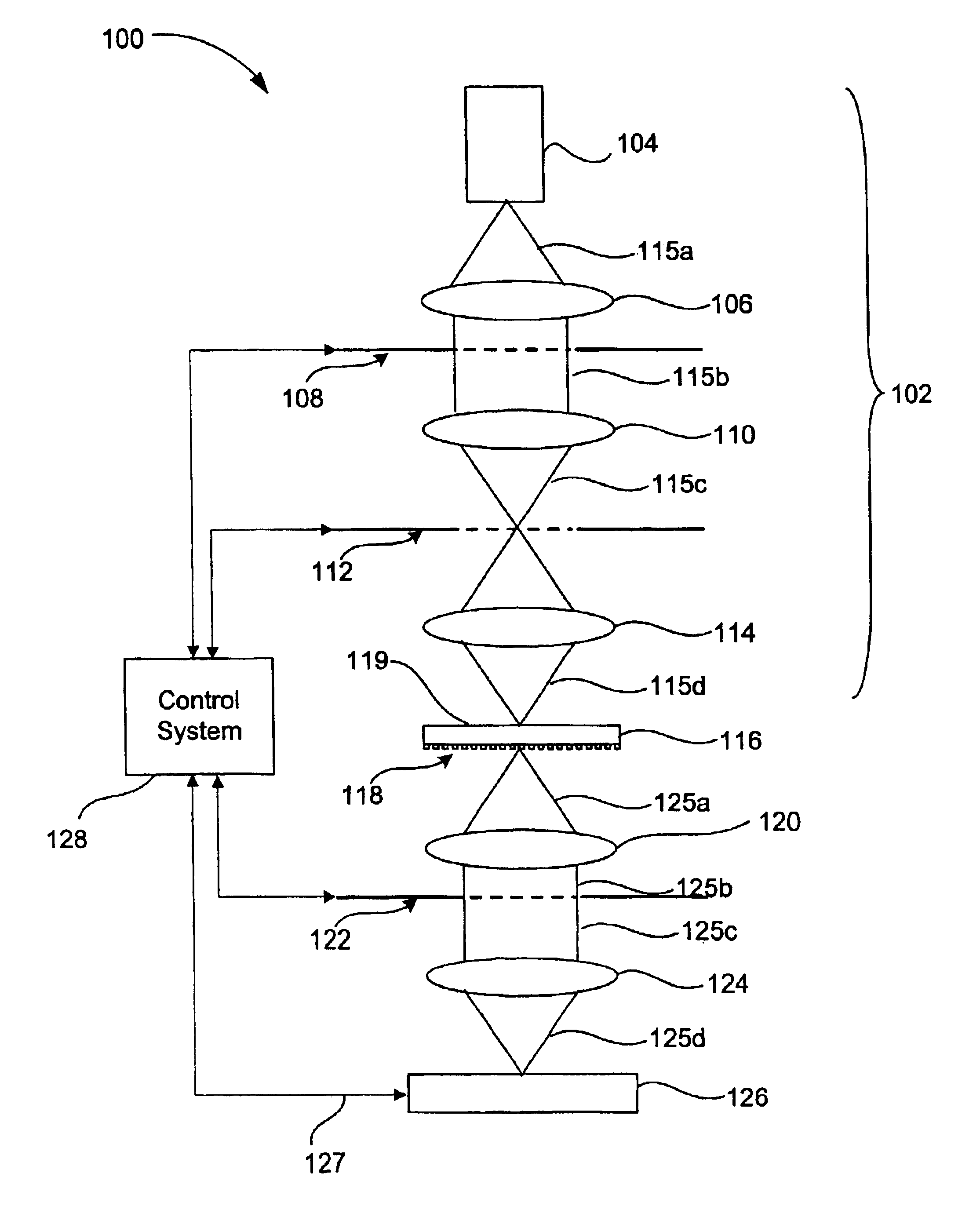
FIG. 1 is a diagrammatic representation of a transmission mode inspection system 100 having transmission type spatial light modulators (SLMs) in accordance with the present invention. As shown, the system 100 includes a beam generator 102 for directing an incident optical beam 115 onto sample 116. At least a portion of the incident beam 115 is directed from the sample 116 as an output beam 125 through imaging optics (e.g., 120 and 124) towards detector 126. The detector 126 is generally operable to generate a detected signal 127 that may be transmitted to control system 128 for further processing. Typical features of the control system 128 may include one or more of the following tasks: generating an image of sample 116 based on the detected signal 127, analyzing the detected signal to determine a characteristic (e.g., defect identification) of the sample, and controlling various components of the inspection system 100.

The beam generator 102 may include any suitable light source and...

second embodiment

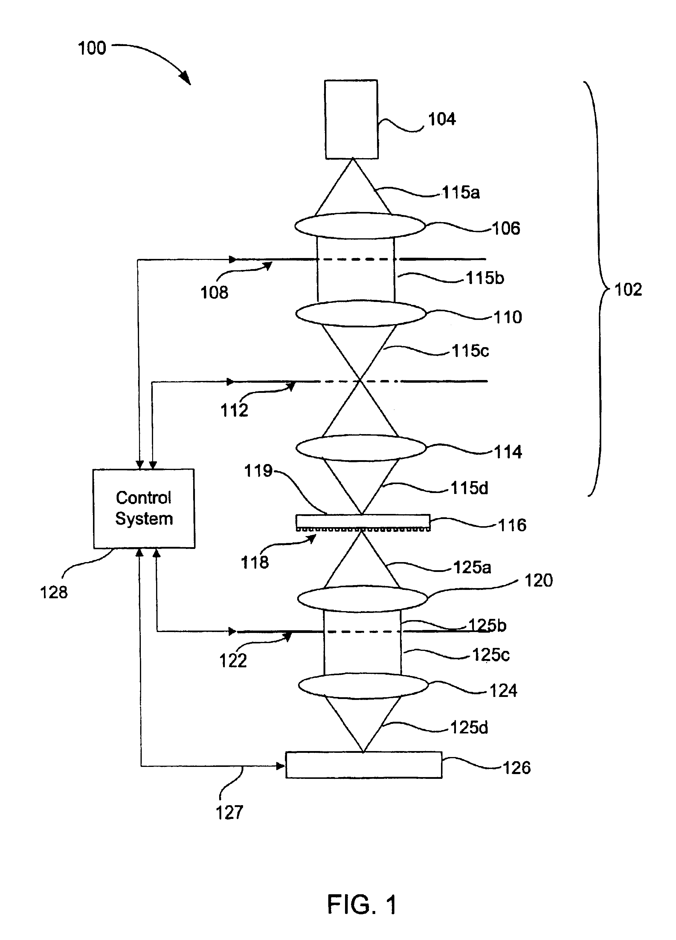
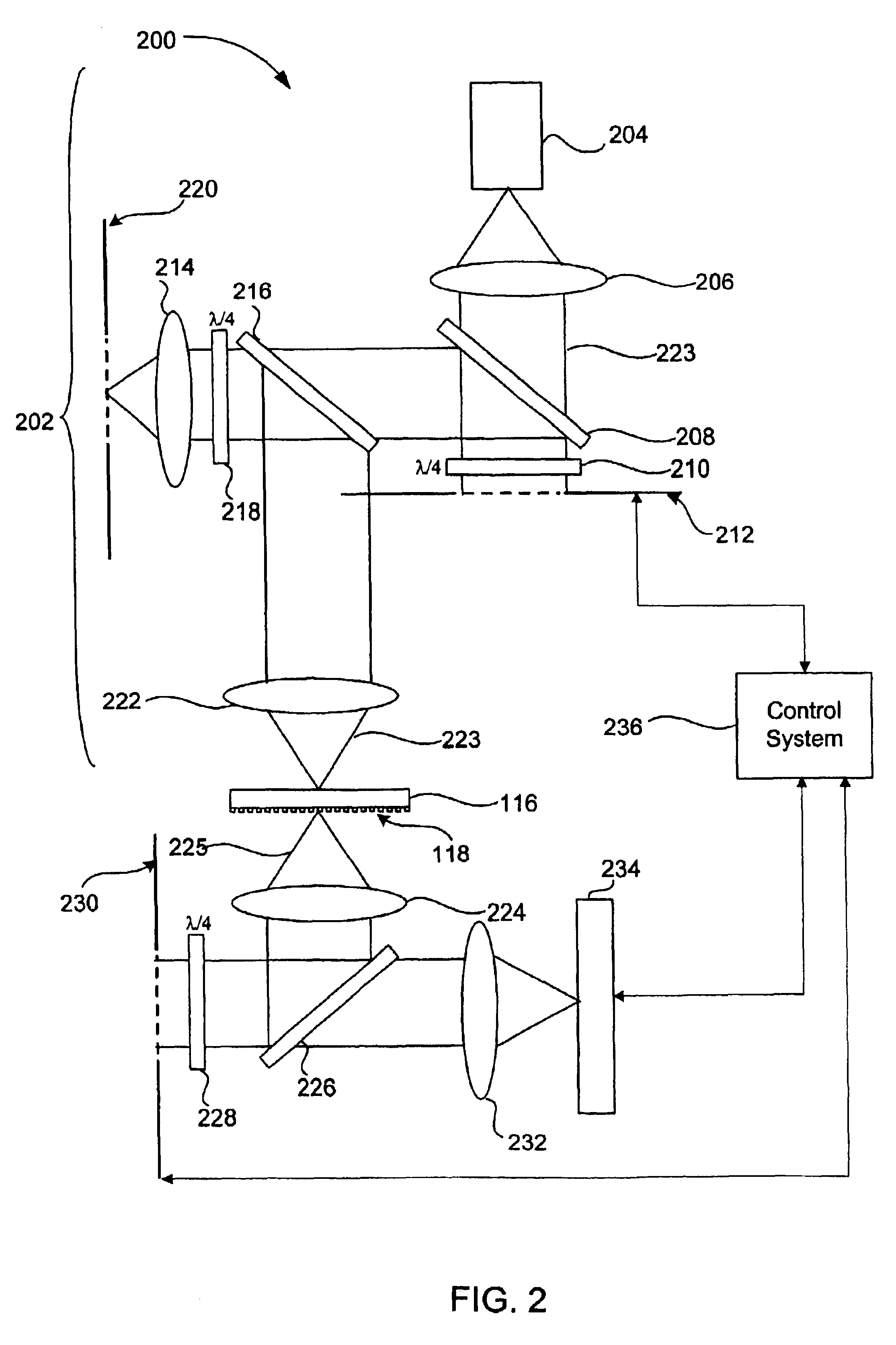
FIG. 2 is a diagrammatic illustration of a transmission mode system 200 having reflective type SLM's in accordance with the present invention. Similar to the system of FIG. 1, the system 200 of FIG. 2 includes a beam generator 202 having collimating lens 206, relay lens 214, and focusing lens 222 for directing incident beam 223 onto sample 116 having a pattern on surface 118.

In contrast to the system of FIG. 1, the system 200 of FIG. 2 includes SLM's which are reflective instead of transmissive. Accordingly, the system includes several additional components for reflecting either the incident beam or the output beam off each SLM. As shown, incident beam 223 passes through polar beam splitter (PBS) 208, through one quarter wavelength plate 210 onto reflective SLM 212. The SLM 212 may be configured to alter the illumination profile of the incident beam. The incident beam also reflects off of the SLM 212 and passes through the quarter wavelength plate 210. The quarter wavelength plate 2...

third embodiment

FIG. 3 is a diagrammatic representation of a reflective mode system 300 having reflective type SLM's in accordance with the present invention. In an alternative embodiment, the reflective system of FIG. 3 may be combined with the transmission type inspection system of FIG. 1 or 2 into a dual mode inspection system In this illustrated system 300, the incident beam is reflected from sample 116 onto detector 336, instead of being transmitted through such sample as in FIGS. 1 and 2. As illustrated, an incident beam is generated by beam source 304 and directed towards lens 306, which collimates the incident beam. The collimated incident beam is then reflected off PBS 308, through quarter wavelength plate 310, onto reflective SLM 312. The SLM 312 may be configured to adjust the illumination profile of the incident beam and then reflect the incident beam back through quarter wavelength plate 310. The incident beam then passes through PBS 308, through PBS 316 and quarter wavelength plate 31...


PUM

PropertyMeasurementUnit
phaseaaaaaaaaaa
angleaaaaaaaaaa
reflection inspectionaaaaaaaaaa

Abstract

Disclosed are methods and apparatus for altering the phase and/or amplitude of an optical beam within an inspection system using one or more spatial light modulator(s) (SLMs). In one embodiment, an apparatus for optically inspecting a sample with an optical beam is disclosed. The apparatus includes a beam generator for directing an incident optical beam onto the sample whereby at least a first portion of the incident optical beam is directed from the sample as an output beam and a detector positioned to receive at least a portion of the output beam. The detector is also operable to generate an output signal based on the output beam. The apparatus further includes one or more imaging optics for directing the output beam to the detector and a programmable spatial light modulator (SLM) positioned within an optical path of the incident or output beam. The SLM is configurable to adjust a phase and/or amplitude profile of the incident beam or the output beam. The apparatus also has a control system operable to configure the SLM to alter the phase and/or amplitude profile of the incident beam or the output beam. For example, the SLM may be configured to alter the illumination profile of the incident beam to achieve different inspection modes. In another example, the SLM may be configured to alter the phase and/or amplitude profile of the output beam so as to substantially eliminate aberrations produced by the imaging optics. In other embodiments, the apparatus may include two or more SLM's which are configurable to alter the phase and/or amplitude profile of both the incident beam and the output beam.

Description

BACKGROUND OF THE INVENTIONThe present invention relates generally to reticle and integrated circuit design and fabrication systems. More specifically, the invention relates to mechanisms for inspecting reticles and integrated circuits.Generation of reticles and subsequent optical inspection of such reticles have become standard steps in the production of semiconductors. Initially, circuit designers provide circuit pattern data, which describes a particular integrated circuit (IC) design, to a reticle production system, or reticle writer. The circuit pattern data is typically in the form of a representational layout of the physical layers of the fabricated IC device. The representational layout typically includes a representational layer for each physical layer of the IC device (e.g., gate oxide, polysilicon, metallization, etc.). Each representational layer is typically composed of a plurality of polygons that define a layer's patterning of the particular IC device.The reticle writ...

Claims


Application Information

Patent Timeline
Patent Type & Authority Patents(United States)
IPC IPC(8): G01N21/956G01N21/88
CPCG01N21/95607G01M11/0264
Inventor STOKOWSKI, STANSAIDIN, ZAIN K.
Owner KLA TENCOR TECH CORP
Why Eureka
Try Eureka