Electromagnetic antenna apparatus

a technology of electromagnetic radiation and antenna apparatus, applied in the direction of resonant antennas, thermoelectric devices, differential interacting antenna combinations, etc., can solve the problems of resistively loaded antennas, inefficient, lossy and inefficient, existing spheroidal antennas like volcano smoke antennas, etc., and achieves convenient manufacturing and efficient operation.

Inactive Publication Date: 2005-01-18
HUMATICS CORP
View PDF15 Cites 176 Cited by
  • Summary
  • Abstract
  • Description
  • Claims
  • Application Information

AI Technical Summary

Benefits of technology

It is therefore an object of the present invention to provide an apparatus for transferring electromagnetic energy intermediate a host device and a medium adjacent to the apparatus that is efficient in operation and easy to manufacture in productio

Problems solved by technology

Current antenna technology offers several undesirable alternatives to one interested in a small, well-matched, efficient, omni-directional ultra wideband (UWB) short pulse antenna: (1) a self-similar antenna (e.g., a bow tie antenna) that tends to be large and frequency dispersive; (2) a TEM horn antenna that tends to be bulky and highly directive; or (3) a resistively loaded antenna that will necessarily be lossy and inefficient.
Existing spheroidal antennas like the volcano smoke antenna (FIG. 10) are difficult to manufacture.
Existing UWB antennas like the biconical antenna are relatively large and, despite their stable impedance, are not well matched to 50Ω.
Kraus' “double dish” antenna does not meet the performance criteria recognized herein as necessary for optimal performance in an impulse radio application.
The sharp discontinuities in transitioning from a smooth curve to a substantially planar outwardly facing dish surface creates undesirable internal reflections in the “double dish” antenna.
However, they are generally characterized by low directivity and relatively limited bandwidth unless either end loading or distributed loading techniques are employed, in which case bandwidth is increased at the expense of radiation efficiency.
Ringing severely distorts signal pulses and spreads them out in time.
Impulse radio signals are preferably modulated by pulse timing, so such distortion of pulses is not desirable.
Because the radiation centers change location as a function of frequency, these antennas are inherently frequency dispersive; they radiate different frequency components from different parts of the antenna, resulting in a distorted impulse signal.
A significant drawback with such a biconical antenna is that such an antenna is typically implemented with a diameter equal to the wavelength at the lower frequency limit (λI,) thus requiring that the antenna be 0.577λL in height.
Because of similar design limitations, a typical monocone antenna will not provide a good match if it is much less than 0.22λL in diameter.
In any event, a monocone anten

Method used


Image

  • Electromagnetic antenna apparatus
  • Electromagnetic antenna apparatus
  • Electromagnetic antenna apparatus

Examples


Embodiment Construction

Overview of the Invention

The present invention will now be described more fully in detail with reference to the accompanying drawings, in which the preferred embodiments of the invention are shown. This invention should not, however, be construed as limited to the embodiments set forth herein; rather, they are provided so that this disclosure will be thorough and complete and will fully convey the scope of the invention to those skilled in art. Like numbers refer to like elements throughout.

Impulse Radio Basics

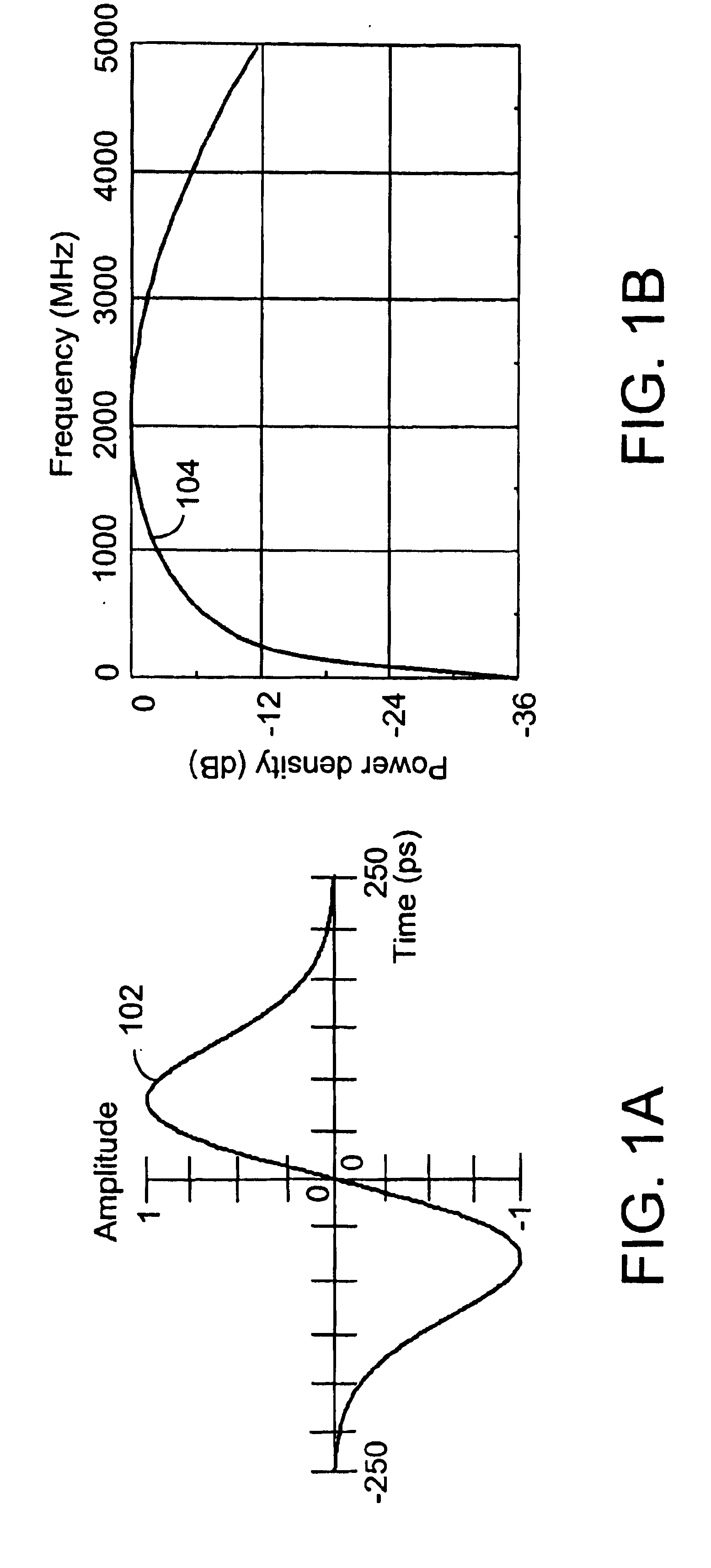
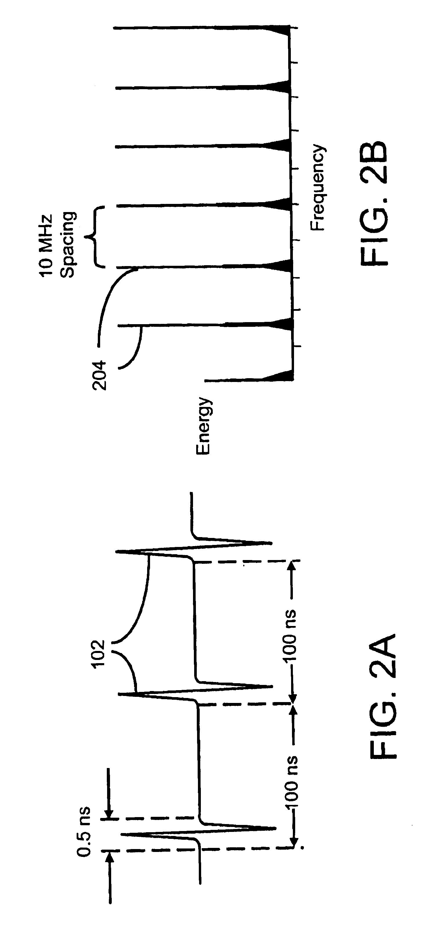
This section is directed to technology basics and provides the reader with an introduction to impulse radio concepts, as well as other relevant aspects of communications theory. This section includes subsections relating to waveforms, pulse trains, coding for energy smoothing and channelization, modulation, reception and demodulation, interference resistance, processing gain, capacity, multipath and propagation, distance measurement, and qualitative and quantitative characteri...


PUM


Abstract

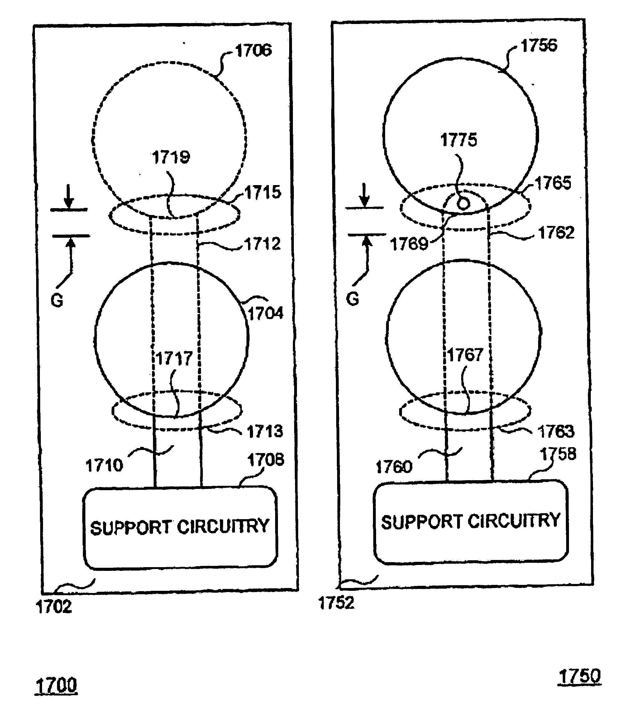
An apparatus for transferring electromagnetic energy intermediate a host device and a medium or free space adjacent to the apparatus in an impulse radio system includes: (a) an energy guiding means for guiding the electromagnetic energy; the energy guiding means is connected with the host device; (b) an electromagnetic energy channeling structure effecting the transferring and including a plurality of gap interfaces; and (c) a transition means for coupling the energy guiding means with at least one gap interface of the plurality of gap interfaces. The transition means conveys the electromagnetic energy intermediate the energy guiding means and the at least one gap interface. The at least one gap interface intersects the transition means in a substantially continuous curve in selected planes intersecting the gap interface and the transition means.

Description

BACKGROUND OF THE INVENTION1. Field of the InventionThe present invention relates generally to electromagnetic energy radiation and reception, and especially relates to electromagnetic energy radiation and reception effected using impulse radio energy. Still more particularly the present invention provides an antenna suited for broadband energy radiation and reception, and particularly well suited for broadband energy radiation and reception employing impulse radio energy.2. Related ArtRecent advances in communications technology have enabled an emerging revolutionary ultra wideband technology (UWB) called impulse radio communications systems (hereinafter called impulse radio).Impulse radio was first fully described in a series of patents, including U.S. Pat. No. 4,641,317 (issued Feb. 3, 1987), U.S. Pat. No. 4,813,057 (issued Mar. 14, 1989), U.S. Pat. No. 4,979,186 (issued Dec. 18, 1990) and U.S. Pat. No. 5,363,108 (issued Nov. 8, 1994) to Larry W. Fullerton. A second generation of...

Claims


Application Information

Patent Timeline
IPC IPC(8): H01Q9/04H01Q21/00H01Q9/16H01Q21/29H01Q9/30H01Q9/00H04B1/69H04B1/7163
CPCH01Q9/005H01Q9/16H01Q21/29H01Q9/30H04B1/7163
Inventor SCHANTZ, HANS GREGORY
Owner HUMATICS CORP
Why Eureka
Try Eureka