Regulated linear purge solenoid valve

Inactive Publication Date: 2005-01-25
3840620 CANADA +1
View PDF6 Cites 28 Cited by
  • Summary
  • Abstract
  • Description
  • Claims
  • Application Information

AI Technical Summary

Benefits of technology

A further aspect relates to an LSPV, including a pressure regulator, that is believed to provide further improvements in purge flow control accuracy over a substantial range of valve operation and under diverse operating conditions.
A still further aspect relates to the provision of certain construct

Problems solved by technology

However, certain geometric factors present at the valve element/valve seat interface may prevent this characteristic from becoming effective until the valve element has unseated a certain minimum distance from the valve seat.
While a CPS valve that incorporates both a linear solenoid and a tapered pintle valve element which is selectively positionable axially within a circular orifice that is circumscribed by the valve seat can exhibit a desired fluid flow rate vs. pintle position characteristic, such characteristic may not become effective until after the pintle has opened a certain minimum amount because of geometric factors at the pintle/seat interface, as noted earlier.
Under the former technique, the mechanism could, by contrast, e

Method used


Image

  • Regulated linear purge solenoid valve
  • Regulated linear purge solenoid valve
  • Regulated linear purge solenoid valve

Examples


Example

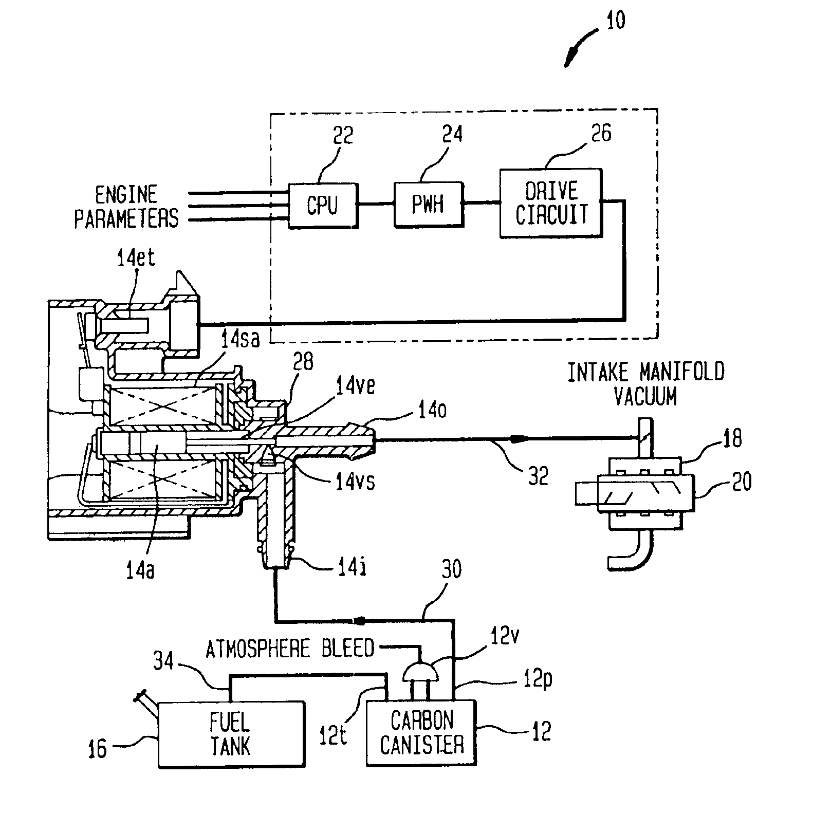
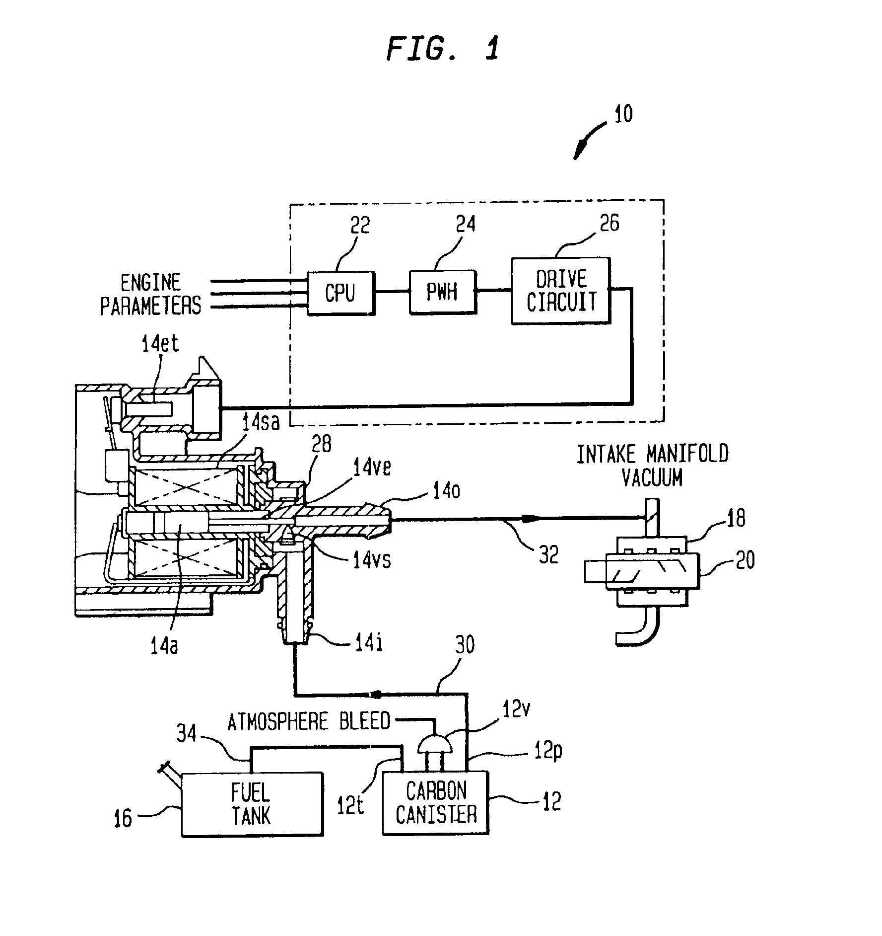
FIG. 1 shows an evaporative emission control system 10 of a motor vehicle comprising a vapor collection canister (carbon canister) 12 and a canister purge solenoid (CPS) valve 14 connected in series between a fuel tank 16 and an intake manifold 18 of an internal combustion engine 20 in a known fashion. An engine management computer 22 supplies a valve control signal as an input to a pulse width modulation (PWM) circuit 24 to create a pulse width modulated signal which is amplified by a drive circuit 26 and applied to electric terminals 14et of valve 14.

Valve 14 comprises a housing 28 having an inlet port 14i that is fluid-coupled via a conduit 30 with a purge port 12p of canister 12 and an outlet port 14o that is fluid-coupled via a conduit 32 with intake manifold 18. A conduit 34 communicates a canister tank port 12t to headspace of fuel tank 16. An operating mechanism comprising a solenoid actuator 14sa is disposed within housing 28 for opening and closing an internal passage that...


PUM


Abstract

A pressure regulator is associated with a solenoid-operated valve that is operated by a pulse waveform at a fundamental frequency substantially greater than the frequency response of the valve mechanism. This substantially attenuates solenoid pulsations and applies a predetermined pressure differential across the valve mechanism to accomplish improved flow control accuracy. The invention is especially advantageous for purging fuel vapor to an intake manifold of an internal combustion engine of an automotive vehicle.

Description

FIELD OF THE INVENTIONThis invention relates generally to emission control valves for automotive vehicles. In one specific aspect, the invention relates to solenoid-operated fluid valves for purging volatile fuel vapors from fuel tanks and vapor storage canisters to internal combustion engines that power such vehicles.BACKGROUND OF THE INVENTIONA known on-board evaporative emission control system comprises a vapor collection canister that collects volatile fuel vapors generated in the headspace of the fuel tank by the volatilization of liquid fuel in the tank and a canister purge solenoid (CPS) valve for periodically purging collected vapors to an intake manifold of the engine. The CPS valve comprises a solenoid actuator that is under the control of a microprocessor-based engine management system.During conditions conducive to purging as determined by the engine management system on the basis of various inputs to it, evaporative emission space that is cooperatively defined by the ta...

Claims


Application Information

Patent Timeline
IPC IPC(8): F02M25/08F16K31/06G05D7/06
CPCF16K31/0675F02M25/0836
Inventor COOK, JOHN EDWARDBUSATO, MURRAY F.
Owner 3840620 CANADA
Why Eureka
Try Eureka