Comparison apparatus operated at a low voltage

a low-voltage, comparison apparatus technology, applied in the direction of instruments, surgical staples, pulse techniques, etc., can solve the problems of not being able to make the result value, the differential amplifier circuit does not work as a normal amplifier, and cannot apply it to an analog circuit, so as to prevent the change of the property, the effect of stably operating

Inactive Publication Date: 2005-01-25
KEY FOUNDRY CO LTD
View PDF8 Cites 113 Cited by
  • Summary
  • Abstract
  • Description
  • Claims
  • Application Information

AI Technical Summary

Benefits of technology

It is, therefore, an object of the present invention to provide a comparator operated stably even at a low power voltage and preventing its property change caused by a process change.

Problems solved by technology

However, in this case, it is not possible to apply it to an analog circuit because an operation range of the transistor is substantially limited at such low voltage.
That means the circuit for the differential amplifier does not work as a normal amplifier.
Therefore, it is not easy to make the result value of ‘Gm3×Ron5’ become 1.
Accordingly, a stable operation of the circuit in accordance with the prior art can not be guaranteed.

Method used


Image

  • Comparison apparatus operated at a low voltage
  • Comparison apparatus operated at a low voltage
  • Comparison apparatus operated at a low voltage

Examples


Embodiment Construction

Hereinafter, an inventive CMOS comparator outputting one bit digital signal after comparing two analog input signals by alternately performing a track mode operation and a latch mode operation will be described in detail referring to the accompanying drawings.

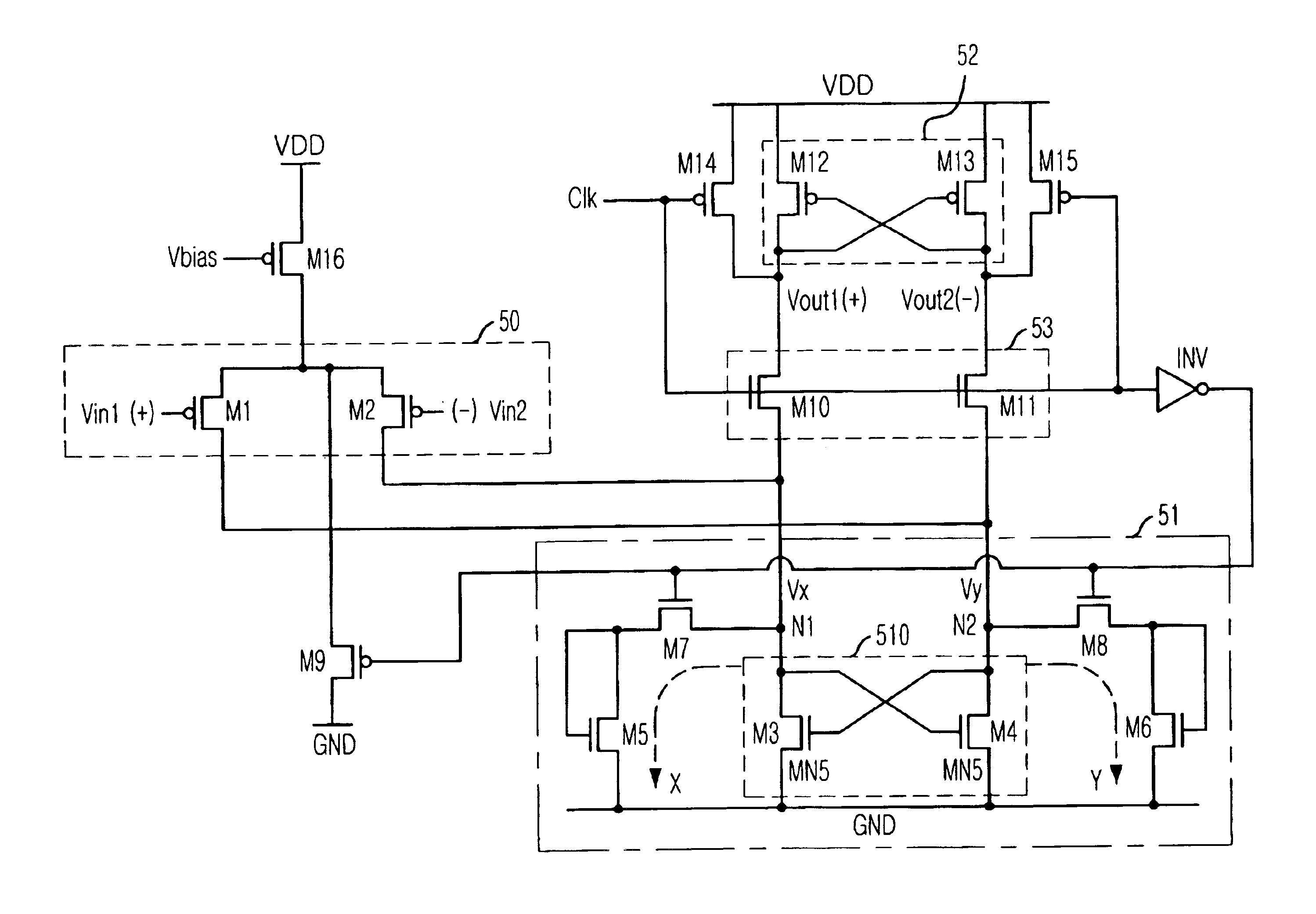
The present invention relates to the CMOS comparator using a low power voltage, for example, 1.8 V. Two groups of transistors are distinctly disposed to have a switch function and a resistor function, respectively. A stable gain without being affected by a voltage or current change or a process can be obtained by forming a ground terminal by using a current pass between two nodes.

FIG. 5 is a detailed circuit diagram of the CMOS comparator used for an analog to digital converter (ADC), wherein the CMOS comparator is designed in accordance with an preferred embodiment of the present invention.

Referring to FIG. 5, the CMOS comparator includes a differential input unit 50, a tracking / latching units 51 a second latching unit 52 and ...


PUM


Abstract

The present invention provide an CMOS comparator outputting one bit digital signal after comparing two analog input signals through alternately performing a track mode operation and latch mode operation decided by a clock signal having a constant period, including: a latching unit having the main/sub input terminal; a first switching transistor having the clock signal as a gate input and having one end coupled to main input terminal; a first load transistor diode-connected to the other end of the first switching transistor and a ground end; a second switching transistor having a gate receiving the clock signal as a gate input and one end coupled to the sub input terminal; and a second load transistor diode-connected to the second switching transistor and to the other end of the ground terminal.

Description

FIELD OF THE INVENTIONThe present invention relates to a comparison apparatus; and, more particularly, to the same operated at a high speed and at a low voltage by using an analog signal.DESCRIPTION OF RELATED ARTSRecently, complementary metal oxide semiconductor (CMOS) process techniques are common. Accordingly, a system on chip (SOC) technique integrating a number of circuits on one chip became important to a modern industry. The SOC is integrated with an analog circuit processing an analog signal as well as a large scale digital circuit capable of performing a complicated logic operation. A process technique for large scale integration less than 0.18 μm can be used for a transistor device operated at a low voltage less than 1.8 Voltage (V). A conventional circuit design may be applied to the digital circuit. However, in this case, it is not possible to apply it to an analog circuit because an operation range of the transistor is substantially limited at such low voltage. Accordin...

Claims


Application Information

Patent Timeline
Patent Type & Authority Patents(United States)
IPC IPC(8): H03K3/356H03K3/00A61B17/00A61B17/064A61B17/08A61B17/068A61B17/10A61B17/12A61B19/00
CPCA61B17/0057H03K3/356156A61B17/068A61B17/08A61B17/083H03K3/356139A61B17/064A61B17/0644A61B19/54A61B2017/00004A61B2017/00637A61B2017/00668A61B2017/00672A61B2017/00867A61B2017/0641A61B2017/081A61B90/39
Inventor CHOI, SOO-CHANG
Owner KEY FOUNDRY CO LTD
Why Eureka
Try Eureka