Gas transfer energy recovery and effervescence prevention apparatus and method

a technology of gas transfer energy recovery and effervescence prevention, which is applied in the directions of machines/engines, transportation and packaging, dissolving, etc., can solve the problems of limited natural absorption of oxygen from the air into the water, high microbial oxygen demand, and natural oxygen aeration processes cannot begin to provide sufficient oxygen resources, so as to reduce effervescence loss and minimize energy consumption

Inactive Publication Date: 2005-02-01
ECO OXYGEN TECH
View PDF177 Cites 26 Cited by
  • Summary
  • Abstract
  • Description
  • Claims
  • Application Information

AI Technical Summary

Benefits of technology

Generally, operation of the feed pump and regenerative turbine of the present invention provides a method that results in pressurization within the reactor to enhance gas transfer, minimizes the net energy consumption of the system when compared to prior art systems, and retains highly supersaturated dissolved gas in solution (in the liquid). In some embodiments, such operation further assists in reduction of effervescence loss. The system is also comprised of reliable components, and is not prohibitively expensive to install, maintain, to repair.
In yet another embodiment, the system includes a container having fluid therein. The fluid is the liquid having a low level of dissolved gas therein. The distal end of the outlet houses the regenerative turbine and is submerged in the fluid. These latter two embodiments are particularly useful in reducing effervescence loss.
In two other embodiments, the system further comprises an elevated container for holding the liquid therein, and a bypass means. In one of these embodiments, the pump and turbine comprise a single turbine / pump device capable of pumping liquid into the container via the bypass means and capable of regenerating by moving liquid from the container through the reactor for dissolving gas into the liquid in the reactor. In the other embodiment using an elevated container, the pump means is operable to pump liquid into the elevated container, and the regenerative turbine means is operable to cause flow of the liquid through the bypass means and / or the reactor. Both these embodiments use gravity to pressurize the gas transfer reactor and minimize the energy consumed and have other efficiencies.

Problems solved by technology

Normally, in undisturbed bodies of water there is a rather low density of macro and micro organisms in the surface water and the limited natural absorption of oxygen from the air into the water is sufficient to maintain sufficient concentrations of dissolved oxygen in the water to sustain the life processes of that body of water.
However, with increased population density and industrial activity, the associated organic water pollution causes a high microbial oxygen demand that natural oxygen aeration processes cannot begin to provide sufficient oxygen resources.
Odors at aerobic wastewater treatment facilities are associated with the inability to maintain sufficient levels of dissolved oxygen (“D.O.”).
Some industries (pharmaceutical, petroleum, and chemical, for example) create significant air pollution problems in the course of aerobically treating their wastewater by the use of conventional aeration systems.
The need for a covered basin arises because conventional aeration systems readily strip the organics / solvents from the aqueous phase, not allowing for a sufficient time to biograde in the liquid.
Many industries must curtail production (to considerable economic detriment) due to insufficient D.O. in the rivers, streams, and canals to which they discharge their treated wastewaters.
Odor and corrosion problems can also occur in the bottom layer of stratified lakes and reservoirs feeding hydroelectric power dams.
The low D.O. levels also result in fish kills.
When high purity oxygen is being transferred into water, issues arise as to handling of dissolved nitrogen (“D.N.”) already in the water.
However, when high purity oxygen is introduced into the water, it results in a reduced D.N. partial pressure that strips the D.N. from the dissolved phase into the gas phase where it, in turn, reduces the percentage oxygen composition.
Thus, the presence of D.N. in the incoming water presents a trade-off situation.
Conversely, if high D.O. levels are to be achieved in the discharge, then the stripped nitrogen in the gas phase has to be wasted to reduce its percentage composition carrying with it a commensurate ratio of oxygen gas and reducing the percentage oxygen absorption efficiency.
However, in conventional pressurization schemes, considerable energy expenditure is involved.
However, because nitrogen gas and other gases are conservative gases, these other gases are not utilized.
If the oxygen absorption efficiency is less than 100%, some of the gas will be wasted from the system, carrying with it some of the oxygen as well as nitrogen stripped from solution.
Even though pressurization can greatly enhance the gas transfer process, it unfortunately also increases the energy consumption required to dissolve the oxygen (in terms of kWatt-hr / ton of D.O.).
While the embodiment of FIG. 1 greatly enhances gas transfer by increasing the pressure within reactor 12, prior art system 10 also greatly increases unit energy consumption.
Little energy is required to move the water through the U-Tube, but the hydrostatic pressurization can be considerable.
However, one disadvantage with use of the U-Tube in that is requires the drilling of a deep shaft that presents a problem particularly if rock is encountered at the site.
In such cases, the drilling of the shaft can cost several hundred thousand dollars, and, in many instances, is prohibitively expensive.
Furthermore, above this threshold level, there is a corresponding level of turbulence and time required to make the effervescence occur.
However, it takes the violent turbulence in the throttling to make it effervesce.
Without this violent turbulence, it effervesces inefficiently.

Method used


Image

  • Gas transfer energy recovery and effervescence prevention apparatus and method
  • Gas transfer energy recovery and effervescence prevention apparatus and method
  • Gas transfer energy recovery and effervescence prevention apparatus and method

Examples


second embodiment

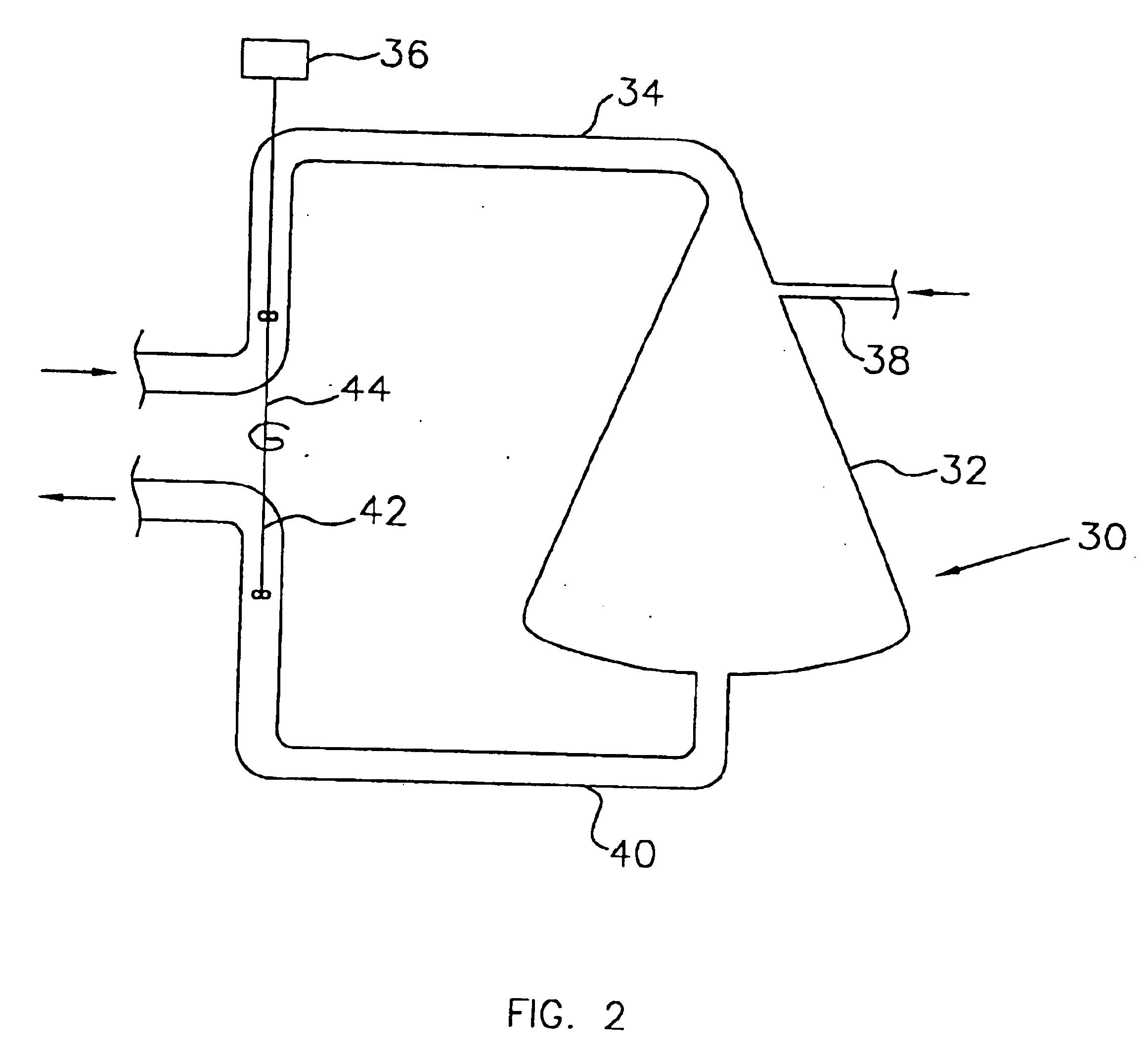
Referring now to FIG. 3, there is shown a schematic view of a gas transfer system according to the present invention having a regenerative turbine driving an electrical generator. In this embodiment, system 50, like system 30 of FIG. 2, includes reactor32, liquid inlet 34, feed pump 36, gas inlet 38, and outlet 40. System 50 also includes regenerative turbine 52 is operatively connected to electric generator 54. During operation, the pressurization of reactor 32 by feed pump 36 also results in operation (by pressure) of regenerative turbine 52. The operation of regenerative turbine 52 results in provision of energy (power) to electric generator 54.

third embodiment

FIG. 4 shows a schematic diagram of a gas transfer system according to the present invention having a regenerative turbine operatively connected by its shaft to the shaft of the feed pump of the system. System 70, like systems 30 and 50 of FIG. 2 and FIG. 3, respectively, includes reactor 32, liquid inlet 34, feed pump 36, gas inlet 38, and outlet 40. System 70 also includes regenerative turbine 72. In this embodiment, feed pump 36 includes shaft 74 which serves as a drive mechanism for feed pump 36. Regenerative turbine 72 includes shaft 76 which serves as a drive mechanism for regenerative turbine 72. Feed pump 36 is coupled with regenerative turbine 72 by v-belt drive 78, operatively connected to shaft 74 of feed pump 36 and to shaft 76 of regenerative turbine 72.

During operation of the embodiment of FIG. 4, operation of feed pump 36 includes rotation of shaft 74. Rotation of shaft 74 includes movement of v-belt drive 78, which in turn includes rotation of shaft 76 of regenerativ...

fourth embodiment

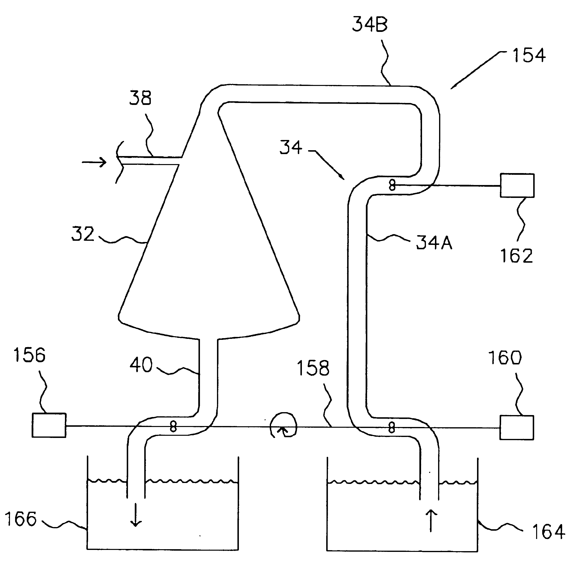
As is discussed in further detail herein, it is advantageous to place the depressurization zone (regenerative turbine or throttling valve) under increased hydrostatic pressure such as at the bottom of a water column to reduce the relative supersaturation, and thus the potential for effervescence. One such example is shown in FIG. 5. FIG. 5 shows a schematic view of a gas transfer system according to the present invention having a regenerative turbine directly coupled with the feed pump of the system and with the regenerative turbine positioned at the bottom of a water column. System 90 includes reactor 32, liquid inlet 34, feed pump 36, gas inlet 38, and outlet 40. In addition, system 90 includes regenerative turbine 92 is connected by shaft 94 to feed pump 36, and regenerative turbine 92 is placed at the bottom of water column 96. The use of water column 96, as discussed below, operates to prevent effervescence of supersaturated discharge.

The effective supersaturation of water pass...


PUM

PropertyMeasurementUnit
saturation concentrationaaaaaaaaaa
dissolvingaaaaaaaaaa
concentrationaaaaaaaaaa

Abstract

A gas transfer system and method for dissolving at least one gas into a liquid. The system includes a gas transfer vessel also known as a reactor. A liquid inlet feed is connected to the reactor for transferring the liquid into the reactor. A gas inlet is connected to the reactor for feeding the gas into the reactor. An outlet is connected to the reactor for transferring the liquid with at least some of the gas therein away from the reactor. The system also includes a feed pump connected to the inlet feed to pressurize the contents of the inlet feed and the reactor, and a regenerative turbine connected to the feed pump and to the outlet. The various embodiments of the gas transfer system use pressurization in the gas transfer vessel to enhance gas transfer therein, minimize the net energy consumption, and retain highly supersaturated dissolved gas in solution. Some embodiments further help to reduce effervescence loss. The method of the present invention utilizes the system of the present invention and operates the feed pump and regenerative turbine to accomplish these advantages.

Description

BACKGROUND OF THE INVENTIONThere are many instances when it is desirable to dissolve a gas, whether soluble or insoluble, into a fluid that may already contain other dissolved gases. For example, the macro and microbial organisms in all rivers, lakes, oceans, and all aerobic wastewater treatment processes are based on the presence of sufficient dissolved oxygen to sustain their life processes. Normally, in undisturbed bodies of water there is a rather low density of macro and micro organisms in the surface water and the limited natural absorption of oxygen from the air into the water is sufficient to maintain sufficient concentrations of dissolved oxygen in the water to sustain the life processes of that body of water. However, with increased population density and industrial activity, the associated organic water pollution causes a high microbial oxygen demand that natural oxygen aeration processes cannot begin to provide sufficient oxygen resources. Thus, artificial aeration mecha...

Claims


Application Information

Patent Timeline
Patent Type & Authority Patents(United States)
IPC IPC(8): B01F3/04B01F15/02F01K25/02F01K25/00B01F1/00C02F3/26F01D5/14
CPCB01F3/0446B01F15/02F01K25/02B01F15/0283B01F15/0243B01F2201/01B01F23/232B01F35/71B01F35/7176B01F35/7544B01F23/2376Y02P70/10
Inventor SPEECE, RICHARD E.
Owner ECO OXYGEN TECH
Why Eureka
Try Eureka