Cooling system for pulsed power electronics

Inactive Publication Date: 2005-02-01
SKYWORKS SOLUTIONS INC
View PDF10 Cites 38 Cited by
  • Summary
  • Abstract
  • Description
  • Claims
  • Application Information

AI Technical Summary

Benefits of technology

The technique of applying PCM to power dissipating circuits can be used to buffer peak power dissipation, and reduce the maximum temperatures, that would otherwise occur. By acting as a heat buffer PCM may also reduce the temperature variations to which a device, operating in pulse mode, is susceptible.
By providing a suitabl

Problems solved by technology

Amplification circuitry and semiconductor devices tend to generate significant amounts of heat.
The continually shrinking packaging, containing the amplification circuitry and devices, has tended to reduce the ability of these devices to dissipate heat through convection.
The space surrounding these devices has become significantly more confined as packaging sizes shrink, thereby reducing the opportunity for convection currents to circulate and remove heat.
Manufacturers have made efforts to reduce or spread the heat within power devices, which tend to generate a significant amount of heat.
Because the effectiveness of the heat sinking diminishes, however, with the air volume available for convection cooling

Method used


Image

  • Cooling system for pulsed power electronics
  • Cooling system for pulsed power electronics
  • Cooling system for pulsed power electronics

Examples


Embodiment Construction

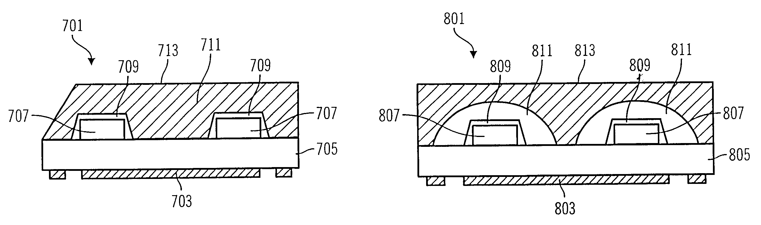
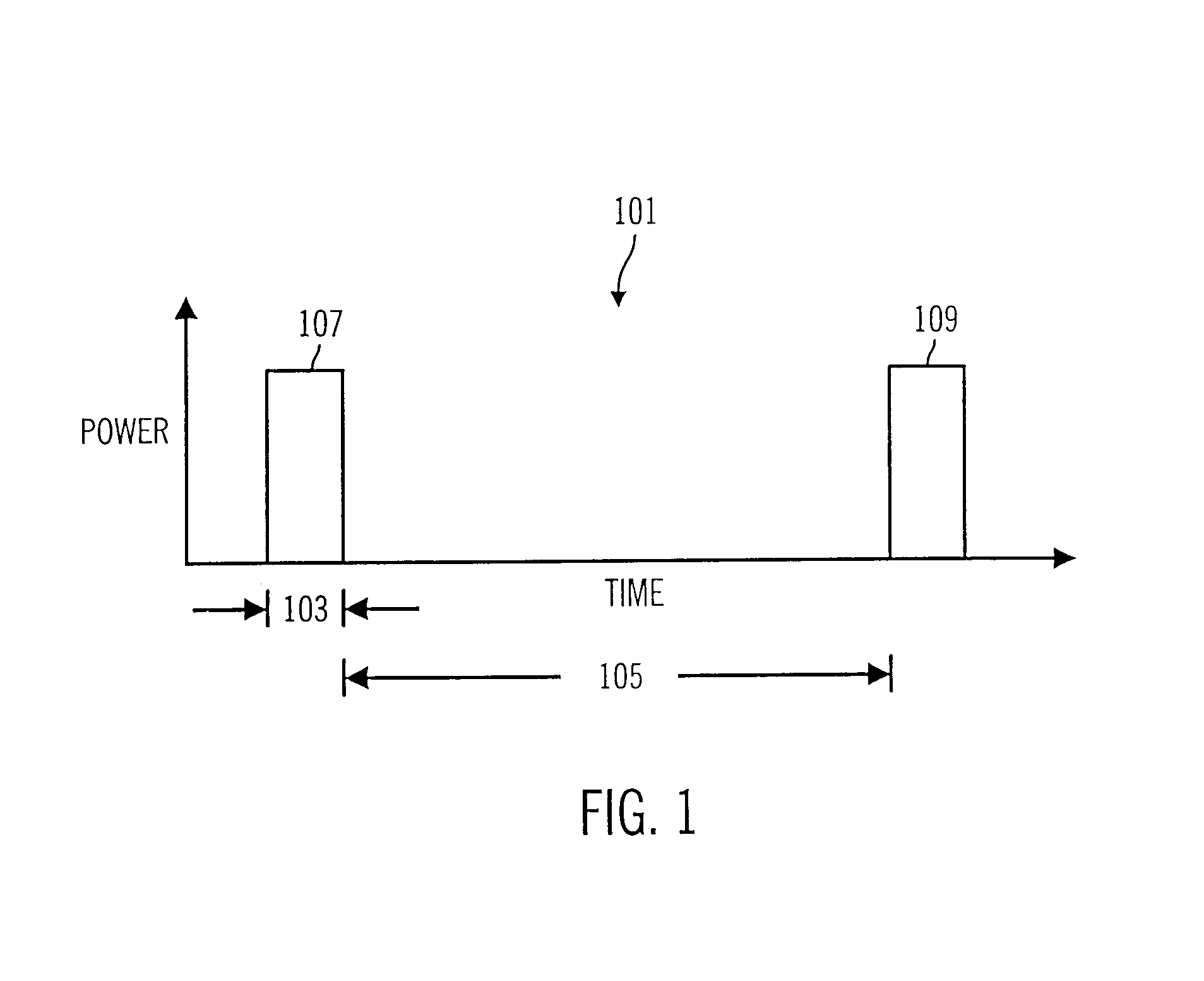
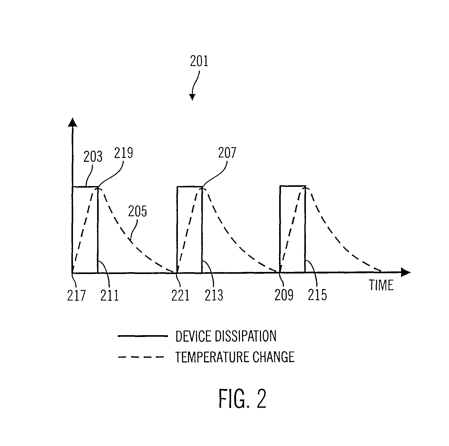
In the following description reference is made to the accompanying drawings which form a part hereof, and in which is shown by way of illustration specific embodiments in which the invention may be practiced. It is to be understood that other embodiments may be utilized as structural changes may be made without departing from the scope and inventive concepts of the present disclosure.

Embodiments of the present invention relate, generally, to power dissipation within pulsed power devices, and in particular embodiments to power dissipation within pulsed power devices within portable communication systems.

Power amplification devices, and devices which dissipate significant amounts of power, according to embodiments of-the invention, may be employed in a variety of portable electronic systems. However for the purposes of simplifying this disclosure, preferred embodiments, are described herein with relation to personal communications systems, such as portable phones, wireless phones, two...


PUM


Abstract

The invention discloses an apparatus for reducing peak temperatures and thermal excursions, of semiconductor devices, particularly in pulsed power applications. The apparatus comprises thermally coupling Phase Change Material (PCM) to the dissipating semiconductor device. PCM absorbs heat and stays at a constant temperature during its phase change from solid to liquid. The PCM melting point is chosen so that it is just below the temperature the device would otherwise achieve. When the device approaches the maximum temperature, the PCM melts, drawing heat from the device and lowering the device's peak temperature. As the device stops dissipating, after its pulse period, the PCM material solidifies releasing the heat it absorbed. The apparatus lowers the peak temperature by absorbing heat when the device is dissipating. The apparatus also keeps the semiconductor device from cooling off as much as it would cool without the apparatus, as the PCM material releases heat during the part of the cycle when it is re-solidifying, i.e. when the pulse power is off. By lowering the peak temperature the device achieves, and increasing the temperature of the device when it is in the off portion of its pulsed power cycle the temperature excursions of the device during operation are reduced. By reducing the temperature swings, that the device sees during operation, the thermal stress is reduced and the reliability of the device is improved.

Description

FIELD OF THE INVENTIONThe present invention relates, generally, to electronic power devices which are operated in a pulsed mode, and, in particular embodiments to personal communications systems, processes and devices which minimize temperature stress within pulsed power circuitry by thermally buffering transient power dissipation.DESCRIPTION OF THE RELATED ARTPortable electronic devices have become part of many aspects of personal, business, and recreational activities and tasks. The popularity of various portable personal electronic communications systems, such as portable phones, portable televisions, and personal pagers, continues to increase. As the popularity of portable electronic systems has increased, so has the demand for smaller, lighter, more powerful and more power efficient devices.Amplification of electronic signals is a function performed in many portable electronic systems. Amplification circuitry and semiconductor devices tend to generate significant amounts of hea...

Claims


Application Information

Patent Timeline
IPC IPC(8): F28D15/00H01L21/02H01L23/28H01L21/50H01L21/44H01L23/29H01L23/427H01L21/48H01L23/34
CPCH01L23/4275Y10S165/902H01L2924/0002H01L2924/00
Inventor LANGARI, ABDOLREZAHASHEMI, SEYED HASSAN
Owner SKYWORKS SOLUTIONS INC
Why Eureka
Try Eureka