Starter pulley with integral clutch

a technology of starter motor and clutch, which is applied in the direction of gearing, road transportation, hoisting equipment, etc., can solve the problems of motor system producing substantial noise levels that could be objectionable, failure of starter motor components, and increased mechanical failure of the system

Inactive Publication Date: 2005-02-01
NTN CORP
View PDF6 Cites 40 Cited by
  • Summary
  • Abstract
  • Description
  • Claims
  • Application Information

AI Technical Summary

Benefits of technology

More specifically, the present invention preferably employs a one-way roller clutch system that is preferably integrated into a pulley drive system (e.g., a multi-groove pulley). The FEAD pulley system is rotatably mounted directly to an electric starter motor. This combined system is preferably mounted on the front of the engine, in series with (e.g., co-planar) the other front-end accessories, such as but not limited to the alternator and water pump systems. By selecting the proper starter motor / crankshaft pulley drive ratio (approximately 3:1), the engine can be cranked at a high enough speed to ensure rapid starting with relatively low noise levels. The roller clutch mechanism preferably includes at least a selectively rotatable inner race, a selectively rotatable outer race having a series of depressions formed on an interior surface thereof, a series of biasable members disposed in the depressions, and a series of rollers disposed between the inner and outer races in proximity to the depressions and held in place by the biasable members. The design of the roller clutch system is such that when the engine is running, the centrifugal force exerted of the rollers overcomes the spring plate force of the biasable members and the rollers move down, or further into, the depressions (e.g., ramps), which are angled, and out of contact with the inner race. This helps to minimize the wear and heat build up that would be present if the rollers were allowed to remain in contact with the inner race of the roller clutch system at all times.
In accordance with a ninth embodiment of the present invention, an engine system is provided, comprising: (1) an engine having a selectively rotatable crankshaft member; (2) a selectively rotatable pulley drive system in physical cooperation with the engine; (3) a belt member in physical cooperation with the pulley drive system, the pulley drive system capable of transmitting a torque force to the belt member so as to cause the crankshaft member to rotate; (4) a starter motor having a selectively rotatable shaft member; and (5) a clutch system, comprising: (a) an inner race member being coaxially disposed about, and in selective physical cooperation with, the selectively rotatable shaft member, the inner race member being capable of rotating in response to a torque force transmitted from the selectively rotatable shaft member; (b) an outer race member being coaxially disposed about, and in selective physical cooperation with, the inner race member, the outer race member being capable of rotating in response to a torque force transmitted from the inner race member, the outer race having at least one area defining a depression formed on an interior surface thereof, the outer race member in physical cooperation with the pulley drive system, the outer race member capable of transmitting a torque force to the pulley drive system; (c) at least one biasable member in physical cooperation with at least a portion of a surface of the depression; and (d) at least one roller member disposed between the inner and outer race members, the at least one roller member in physical cooperation with the at least one biasable member. The at least one roller member is selectively operable so as to physically engage at least a portion of a surface of the outer and inner race members so as to cause a torque force from the inner race member to be transmitted to the outer race member. The at least one roller member is capable of transmitting a compressive force to the at least one biasable member so as to cause the at least one roller member to physically disengage from at least a portion of the surface of the inner race member so as to prevent a torque force from the outer race member to be transmitted to the inner race member.

Problems solved by technology

This particular type of system usually rotates the engine too slowly to prevent an undesirable delay in the engine start-up process.
Additionally, these conventional starter motor systems produce substantial noise levels that could be objectionable with high-frequency usage.
Furthermore, the high frequency of use may cause durability problems with these conventional gear driven systems, thus leading to failure of the components of the starter motor system with resulting warranty claims.
If a conventional starter motor system were to be employed in such an automobile, the wear on the individual components of the starter motor system, especially the pinion gear and the ring gear, would be rather excessive and would possibly lead to increased mechanical failures of the system.

Method used


Image

  • Starter pulley with integral clutch
  • Starter pulley with integral clutch
  • Starter pulley with integral clutch

Examples


Embodiment Construction

The following description of the preferred embodiment(s) is merely exemplary in nature and is in no way intended to limit the invention, its application, or uses.

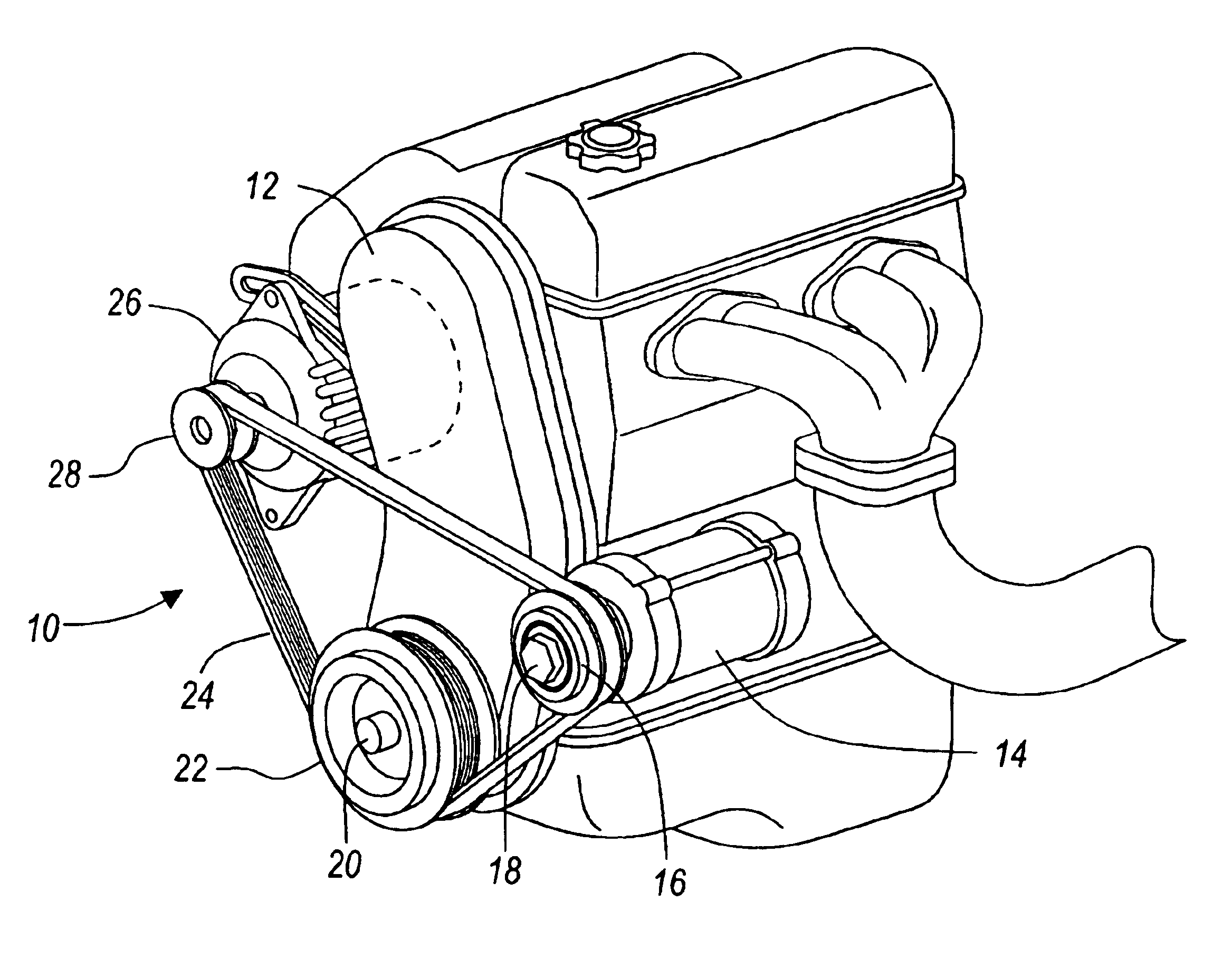
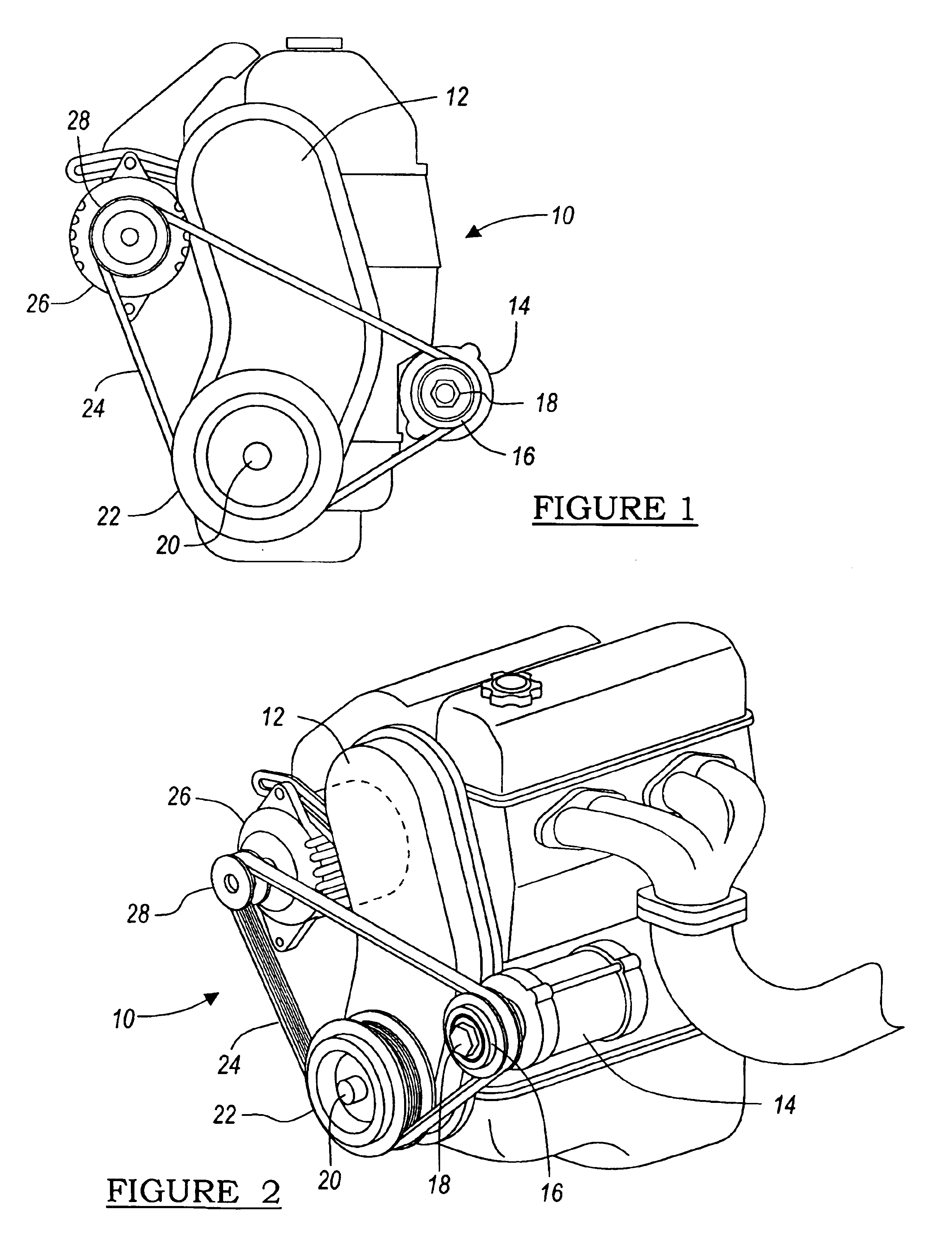
Referring generally to the drawings, and specifically to FIGS. 1-2, there is shown an illustrative engine system 10, in accordance with the general teachings of the present invention. The engine system 10 of the present invention preferably includes, but is not limited to, an engine 12, a starter motor system 14, a selectively rotatable clutch system 16, a selectively rotatable front-end accessory drive system 18, a selectively rotatable crankshaft member 20, a selectively rotatable crankshaft drive system 22, a selectively rotatable drive belt member 24, an accessory system 26, and a selectively rotatable accessory drive system pulley 28.

The engine 12 is preferably an internal combustion engine, such as, but not limited to a gasoline or diesel engine. Furthermore, the engine 12 can be incorporated into high fuel efficiency...


PUM


Abstract

Starter motor systems are described, wherein the systems include a unidirectional clutch system that cooperates with a pulley system to start an internal combustion engine through the front-end accessory drive system. The starter motor systems are especially well suited for new, high fuel efficiency automobiles in which the engine is shut down (e.g., when the automobile stops) and subsequently started (e.g., when the accelerator pedal is depressed).

Description

FIELD OF THE INVENTIONThe present invention relates generally to a vehicle starter motor and more particularly to a new and improved unidirectional (i.e., one-way) clutch system for use with a drive pulley of a vehicle starter motor system.BACKGROUND OF THE INVENTIONPresently, conventional starter motor systems for automotive applications typically employ an electric starter motor with a Bendix-drive pinion gear to drive a relatively large diameter ring gear attached to the engine crankshaft. This particular type of system usually rotates the engine too slowly to prevent an undesirable delay in the engine start-up process. Additionally, these conventional starter motor systems produce substantial noise levels that could be objectionable with high-frequency usage. Furthermore, the high frequency of use may cause durability problems with these conventional gear driven systems, thus leading to failure of the components of the starter motor system with resulting warranty claims.The afor...

Claims


Application Information

Patent Timeline
Patent Type & Authority Patents(United States)
IPC IPC(8): F02N15/02F02N11/08F02B67/06F16D41/06F16H7/14F16H55/36
CPCF02N15/023F02N15/026F02N11/0814Y10T74/13F16H55/36Y02T10/76F16H7/14F16D41/066
Inventor MILLER, JOHN R.
Owner NTN CORP
Why Eureka
Try Eureka