
Engineered material buoyancy system and device

a technology of buoyancy system and engineered material, which is applied in the direction of special-purpose vessels, vessel construction, and borehole/well accessories, etc., can solve the problems of prohibitively high stiffening and avoiding excessive and damaging dynamic responses to wave forces, and inconvenient conventional offshore oil production methods using fixed truss platforms, etc., to achieve the effect of improving hydrodynamic performan

Inactive Publication Date: 2005-02-01
TECH FRANCE SA
View PDF44 Cites 46 Cited by
  • Summary
  • Abstract
  • Description
  • Claims
  • Application Information

AI Technical Summary

Benefits of technology

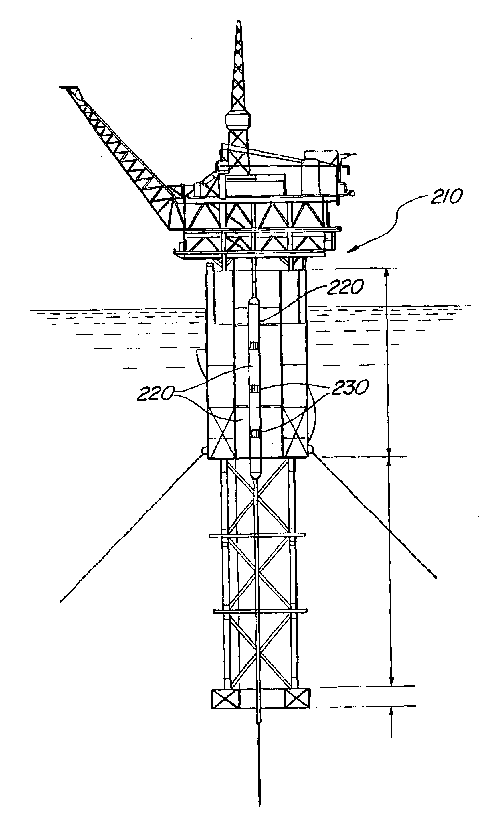
Further embodiments comprise an apparatus for providing buoyancy to a submerged riser attached at its lower end to a well head on the sea floor. That apparatus comprises a plurality of submerged buoyancy modules associated with the riser for imparting an upward buoyancy force to the riser, wherein each buoyancy module is hollow and has an elongated shape with a longitudinal axis and is vertically oriented, the longitudinal axis of the buoyancy module being generally parallel to the longitudinal axis of the riser, some of the buoyancy modules being disposed at different vertical elevations along the riser in an arrangement so as to provide improved hydrodynamic performance to the riser, wherein each buoyancy module comprises a layered exterior wall, wherein each layer of the wall has a specific function, and wherein the layers include one or more of hoop layers to resist internal and external pressure, axial layers to carry axial loads, polymeric liners to prevent fluid leakage through the wall, and selective reinforcing layers to provide damage tolerance at assembly contact locations and at buoyancy load transfer locations, and straps for attaching the buoyancy modules to the riser, the straps passing around the outer circumference of the buoyancy modules.

Problems solved by technology

Conventional offshore oil production methods using a fixed truss type platform are not suitable for these water depths.
Stiffening them to avoid excessive and damaging dynamic responses to wave forces is prohibitively expensive.
Flexible and SCR type production risers require the wellhead control valves to be placed on the seabed where access and maintenance is expensive.
TTR tensioning systems are a technical challenge, especially in very deep water where the required top tensions can be 1000 kips or more.
These types of vessels are only suitable for flexible risers.
Semi-submersibles use TTRs for drilling risers, but these must be disconnected in extreme weather.
As tensions and stroke requirements grow, these active tensioners become prohibitively expensive.
They also require large deck area, and the loads have to be carried by the FPS structure.
This issue becomes increasingly more critical as production moves to deeper water because the amount of buoyancy required increases with water depth.
The challenge is to achieve the buoyancy needed while keeping the length of the cans within the confines of the centerwell, and the diameters to reasonable values.
Adding air to the annulus is efficient use of the stem volume, but the amount of buoyancy can be so large that if a leak occurs there could be damage to a riser.
Making the buoyancy cans integral with the risers has been used, but this requires a relatively small can diameter for deployment with the surface rig, and the structural connections between the cans and the riser are difficult to design.
The buoyancy cans are typically constructed out of steel and their weight can be a significant design issue.

Method used


Image

  • Engineered material buoyancy system and device
  • Engineered material buoyancy system and device
  • Engineered material buoyancy system and device

Examples


Embodiment Construction

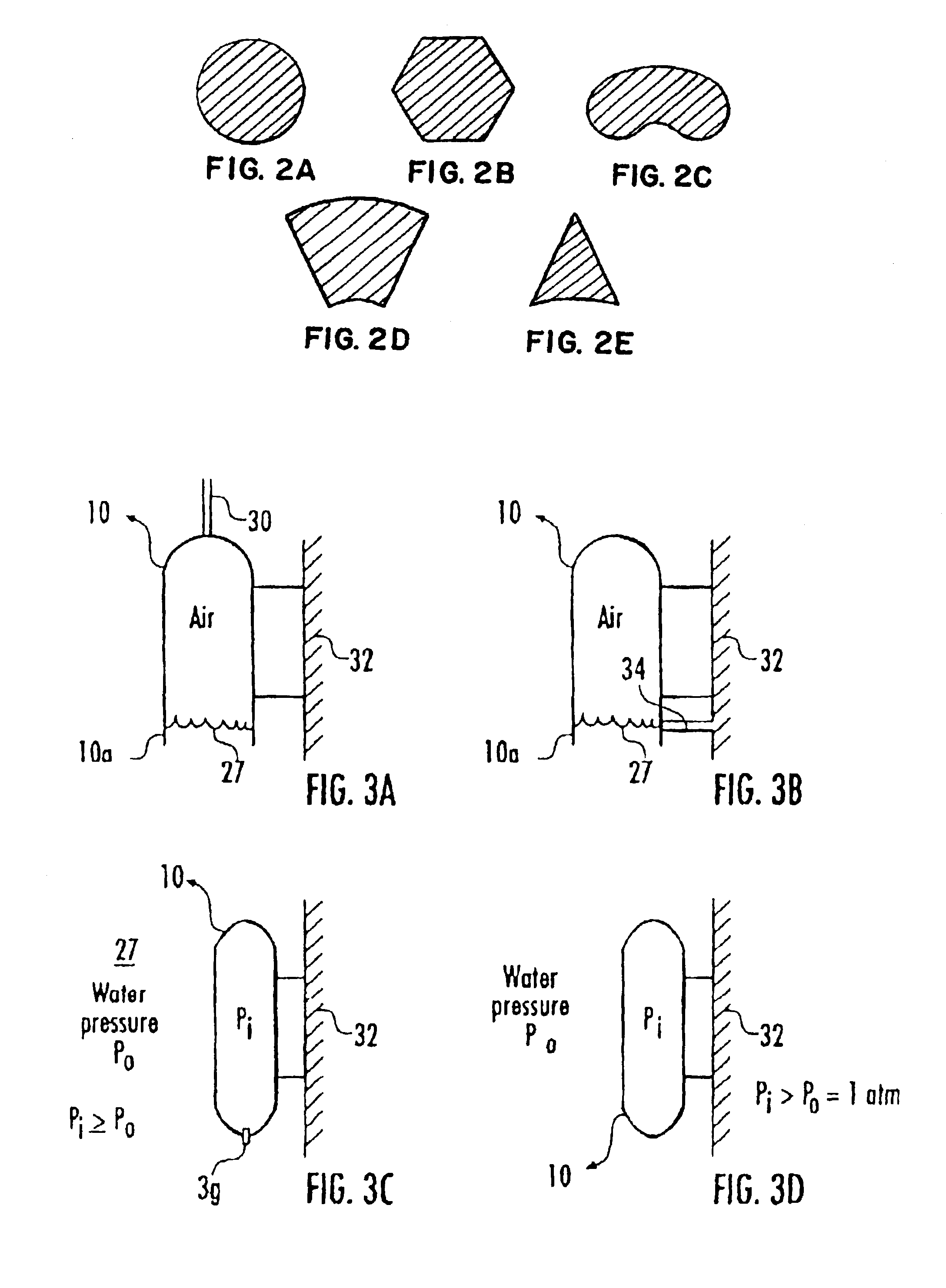
According to one example embodiment of the invention, airtight composite buoyancy modules (CBMs) provide buoyancy to attached objects submerged underwater. Different sizes and shapes of CBMs are attached in various embodiments to, for example, production risers, drilling riser, catenary risers, air cans, and stem pipe.

In the example embodiments illustrated, buoyancy is provided by trapping air inside structures of engineered materials (for example: glass fiber / polymeric resin, carbon fiber / polymeric resin, hybrid glass / carbon fiber polymeric resin, engineered rubber reinforced with nylon or steel fibers).

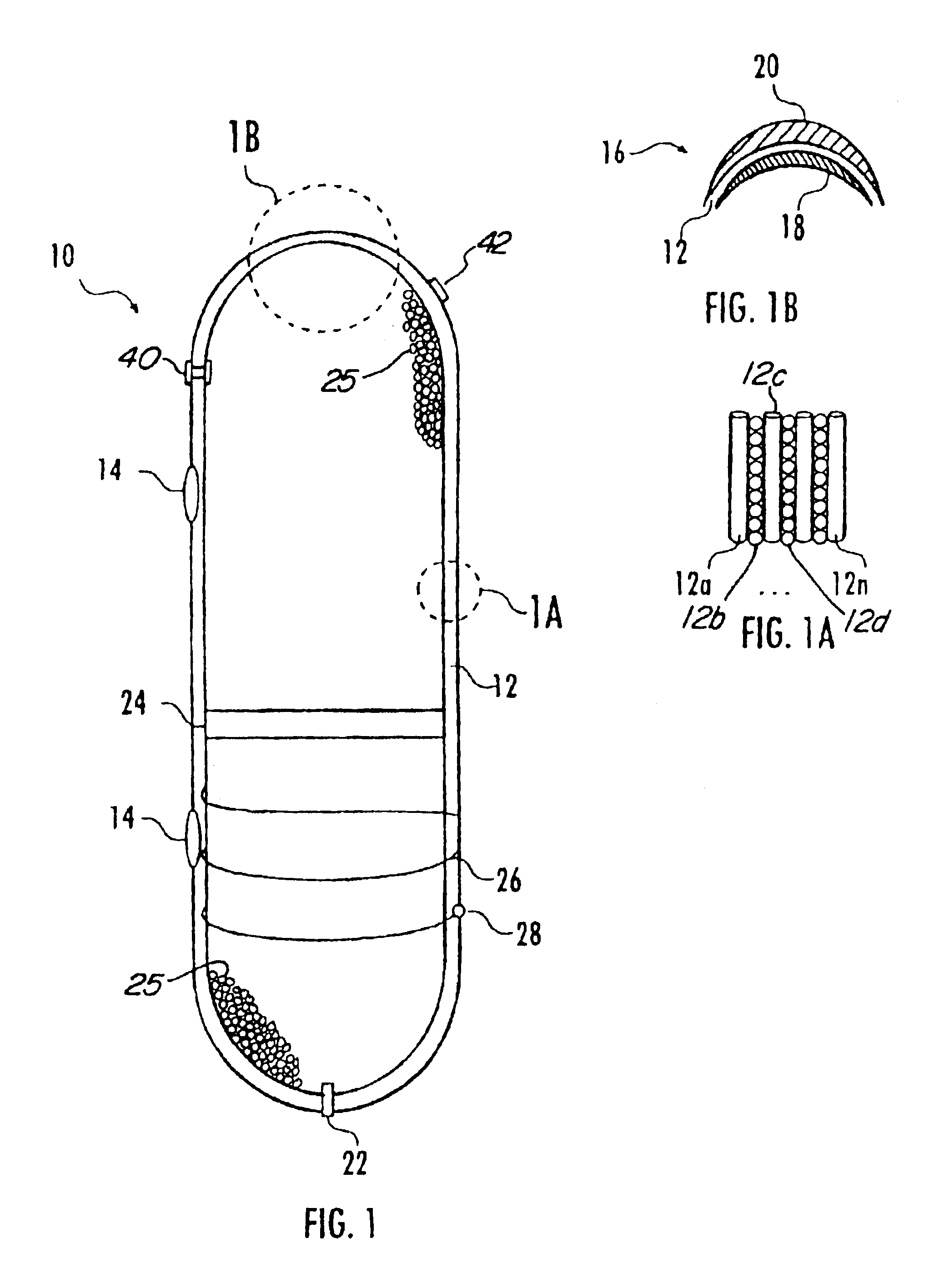
Referring now to FIG. 1, a CBM 10 is seen, having a wall 12 of layers 12a-12n (seen in FIG. 1a) of engineered materials. Various of the layers 12a-12n have differing functions. For example, some of the layers 12b and 12d comprise substantially reinforced hoop layers (substantially horizontal orientation of fiber) to resist internal and external pressure. Other layers 12a and 12c com...


PUM

PropertyMeasurementUnit
Water depthsaaaaaaaaaa
lengthaaaaaaaaaa

Abstract

There is provided a buoyancy system for a structure having at least one component being substantially stationary with respect to the bottom of a water covered area. The system comprises a set of buoyancy modules of engineered materials to apply an identified amount of buoyancy. The set of buoyancy modules is attached to the structure at a set of buoyancy load transfer locations. The set of buoyancy modules comprises layers of the engineered materials. The engineered materials comprise a substantially reinforced axial layer, a substantially reinforced hoop layer; and a leak prevention layer.

Description

STATEMENT REGARDING FEDERALLY SPONSORED RESEARCH OR DEVELOPMENTNot applicable.BACKGROUND OF THE INVENTIONThe present invention relates to the application of buoyancy to objects used in large vessel and platform operations.Vast oil reservoirs have recently been discovered in very deep waters around the world, principally in the Gulf of Mexico, Brazil and West Africa. Water depths for these discoveries range from 1500 ft to nearly 10,000 ft. Conventional offshore oil production methods using a fixed truss type platform are not suitable for these water depths. These platforms become dynamically active (flexible) in these water depths. Stiffening them to avoid excessive and damaging dynamic responses to wave forces is prohibitively expensive.Deep water oil and gas production has thus turned to new technologies based on floating production systems. These systems come in several forms, but all of them rely on buoyancy for support and some form of a mooring system for lateral restraint aga...

Claims


Application Information

Patent Timeline
Patent Type & Authority Patents(United States)
IPC IPC(8): B63B5/00B63B5/24B63B43/00E21B17/00E21B17/01F16L1/12F16L1/24B63B35/44B63B21/50B63B21/00
CPCB63B43/00E21B17/012B63B5/24F16L1/24B63B35/4406B63B21/502
Inventor KARAYAKA, METINSTANTON, PAUL N.
Owner TECH FRANCE SA
Learn More