System and method of forming structural assemblies with 3-D woven joint pre-forms

a technology of woven textiles and pre-forms, which is applied in the direction of machine/engine, packaging, and surface pretreatment for adhesion processes, etc. it can solve the problems of high cost of hand woven textiles, low peel strength of composite resins, and limited out-of-plane load capacity of conventional composite structural joints (co-cured, bonded or bolted), so as to eliminate the need for expensive tooling and fine tolerances, the effect of increasing the structural strength of pre-form

Inactive Publication Date: 2005-02-01
LOCKHEED MARTIN CORP
View PDF14 Cites 94 Cited by
  • Summary
  • Abstract
  • Description
  • Claims
  • Application Information

AI Technical Summary

Benefits of technology

The present invention provides an important technical advantage over prior systems and methods of forming complex composite structures. The present invention provides a robust joint between two pre-cured composites or metallic sub-assemblies. By simultaneously co-bonding sub-assemblies to 3-D woven textile pre-forms structural strength is increased.
Additionally, the present invention provides another important technical advantage by eliminating the need for expensive tooling and fine tolerances to achieve uniform bondlines critical for structural performance.
Yet another technical advantage provided by the present invention is that pressure intensifiers or overpresses used can be inexpensively manufactured as an exact fit is not required as is needed by conventional bonding or co-curing.
Additionally, the present invention provides another important technical advantage by forcing uncure...

Problems solved by technology

Conventional composite structural joints (co-cured, bonded or bolted) are severely limited in out of plane load capacity (as generated by fuel pressure loads in a wing box or kick loads at structural discontinuities).
Typical composite resins have good tension and shear strengths, but very low peel strength.
However, due to high cost of the hand woven textiles, this technology was not used until the early 1990s when the F-2 program automated weaving of the deltoid insert shown in FIG.
While strength is increased, this application is still limited by expensive tooling and processing required for co-cure fabrication of the F-2 composite wing.
Also, the joint is still prone to delaminating up the middle.
This j...

Method used


Image

  • System and method of forming structural assemblies with 3-D woven joint pre-forms
  • System and method of forming structural assemblies with 3-D woven joint pre-forms
  • System and method of forming structural assemblies with 3-D woven joint pre-forms

Examples


Embodiment Construction

Preferred embodiments of the present invention are illustrated in the FIGUREs, like numerals being used to refer to like and corresponding parts of the various drawings.

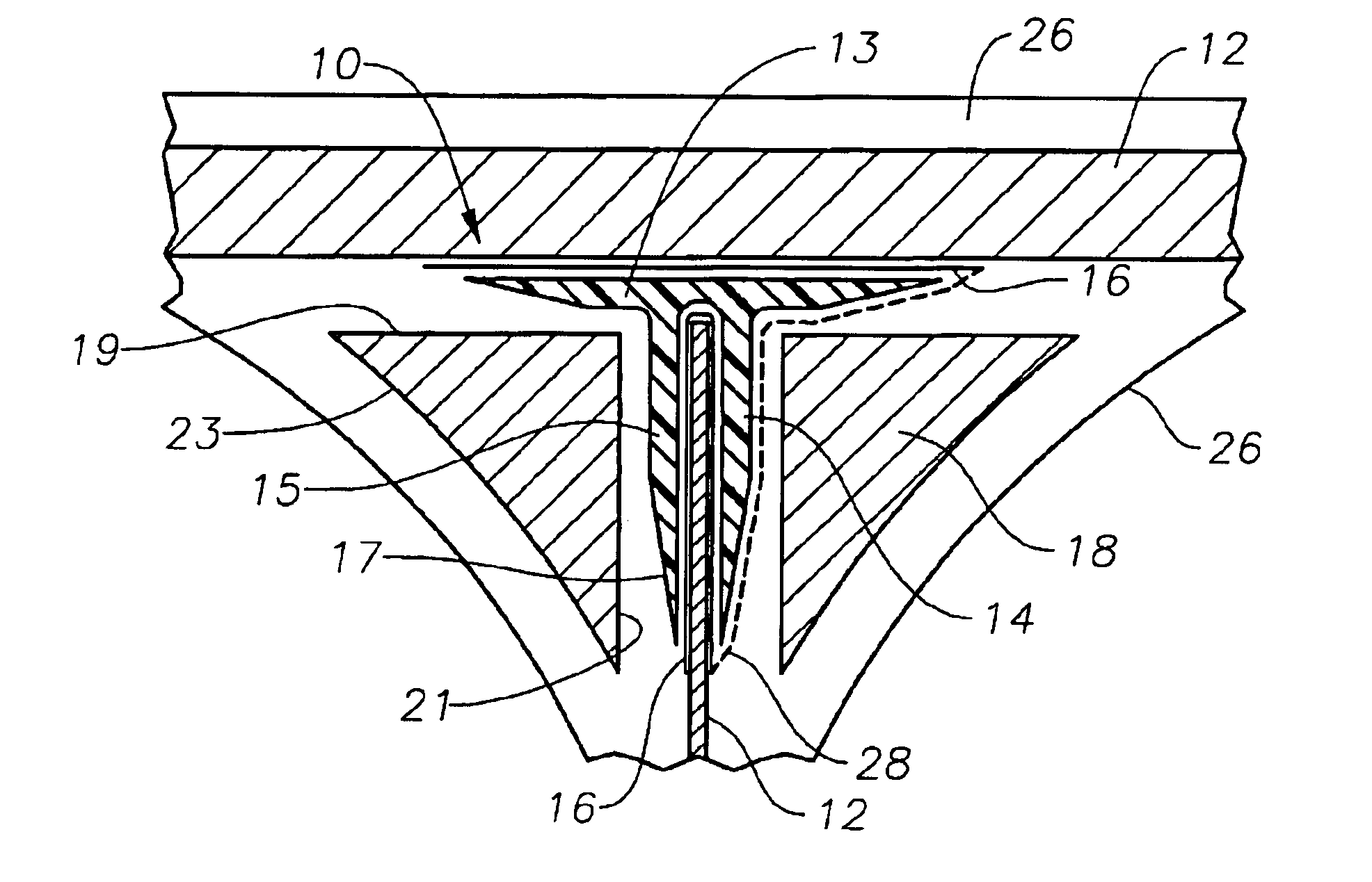
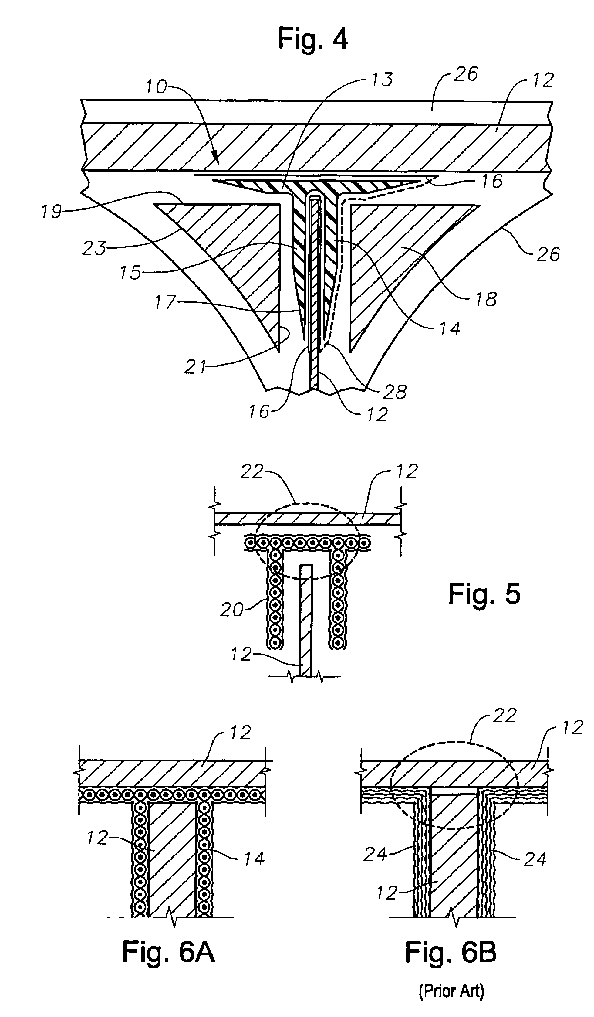
The present invention provides a unique method of assembling structural components as illustrated by FIG. 4. FIG. 4 depicts a structural assembly or part 10. This assembly is formed by various sub-assemblies 12. Subassemblies 12 are typically pre-cured laminated composite structures or metallic structures. Additionally, subassemblies 12 can be constructed from honeycomb sandwich structures or solid monolithic structures. However, the present invention need not be limited to this material type for sub-assemblies 12, other material types such as graphite, fiberglass, metals, Kevlar, and the like, as known to those skilled in the art can be used.

In the most general application, structural assembly 10 is formed by coupling at least one sub-assemblies 12 with an uncured pre-form 14 in a curing process. In one embodiment o...


PUM

PropertyMeasurementUnit
Angleaaaaaaaaaa
Pressureaaaaaaaaaa
Adhesivityaaaaaaaaaa

Abstract

A system and method for forming structural assemblies with 3-D woven joint pre-forms. The method of the present invention forms complex structural assemblies with pre-formed structures. Adhesive is applied between the preformed structures and uncured 3-D woven textile pre-forms. Then together the preformed structures and uncured resin impregnated 3-D woven textile are cured with heat and/or pressure to form the larger complex structural assemblies.

Description

TECHNICAL FIELD OF THE INVENTIONThe present invention relates generally to systems and methods for fastening sub-assemblies in the formation of larger more complex structures, and more particularly, a system and method for co-bonding structural sub-assemblies with 3-D woven textile pre-forms.BACKGROUND OF THE INVENTIONConventional composite structural joints (co-cured, bonded or bolted) are severely limited in out of plane load capacity (as generated by fuel pressure loads in a wing box or kick loads at structural discontinuities). Joint out of plane loads cause high peel stresses and interlaminar stresses in conventional 2-D laminated composite joints as shown in FIGS. 1A-1E.Typical composite resins have good tension and shear strengths, but very low peel strength.Significant composite joint improvements were developed as far back as 1974 by using 3-D hand woven textile joint inserts in co-cured wing to span joints. However, due to high cost of the hand woven textiles, this technol...

Claims


Application Information

Patent Timeline
IPC IPC(8): B29C65/00B29C70/04B29C70/34B29D31/00B64C1/00B64C1/06B64C3/00B64C3/18B64C3/20B29C35/02B29C65/48B29C65/50B29D99/00
CPCB29C66/4346B29C65/5085B29C65/562B29C66/1142B29C66/43B29C66/43441B29C66/474B29C66/721B29C70/342B29D99/0003B64C1/06B64C3/18B64C3/20B29C65/5071B29C65/483B29C65/5028B29C65/00B29C35/02B29K2313/02B29L2024/006B64C2001/0072B64C2001/0081Y02T50/433B29C66/742B29C66/729B29C65/4835B29C66/7292B29C66/72141B29C66/72525B29C66/71B29C66/112B29C66/1122B29C66/12441B29C66/131B33Y50/00B33Y80/00Y02T50/40B29C70/549B29K2077/10
Inventor SCHMIDT, RONALD P.
Owner LOCKHEED MARTIN CORP
Why Eureka
Try Eureka