Radio-frequency coil array for resonance imaging analysis

a radio-frequency coil array and resonance imaging technology, applied in the field of resonance systems, can solve the problems of unable to satisfy the critical coupling of orthogonal modes in neighboring coils, and arduous process

Inactive Publication Date: 2005-02-01
ADVANCED IMAGING
View PDF12 Cites 38 Cited by
  • Summary
  • Abstract
  • Description
  • Claims
  • Application Information

AI Technical Summary

Benefits of technology

The present invention provides an RF coil array with improved signal-to-noise ratio (S / N) capable of high resolution imaging over the target field-of-view (FOV). The present invention is suitable to reduce the scan times and therefore to further reduce patient discomfort. In accordance with the present invention, a coil is provided which is capable of operating in different modes in one or more frequencies. Moreover, the present invention simplifies the coil construction and its optimization for relative ease of manufacturing.
It is a primary object of the present invention to further improve the signal-to-noise ratio (S / N) of the resonance imaging RF coil sub-system. Another object is to provide a concept of concurrently imaging with the homogenous and RF gradient modes oriented along the coil axis. Another object is to obviate the need for isolating coils geometrically. A further object is to simplify the coil optimization process and provide a coil system that is relatively easy to manufacture.
In the embodiments of the present invention, the first coil has a FOV nearly identical to that of the combined FOV of the second and third RF coils, and overlaps the combined FOV of the second and third coil, such that S / N of all three coils combined is greater than the first coil or greater than the combination of second and third RF coils alone over the imaging FOV. The etched printed circuit design will tremendously ease the coil optimization process when compared to geometrically overlapped coils.
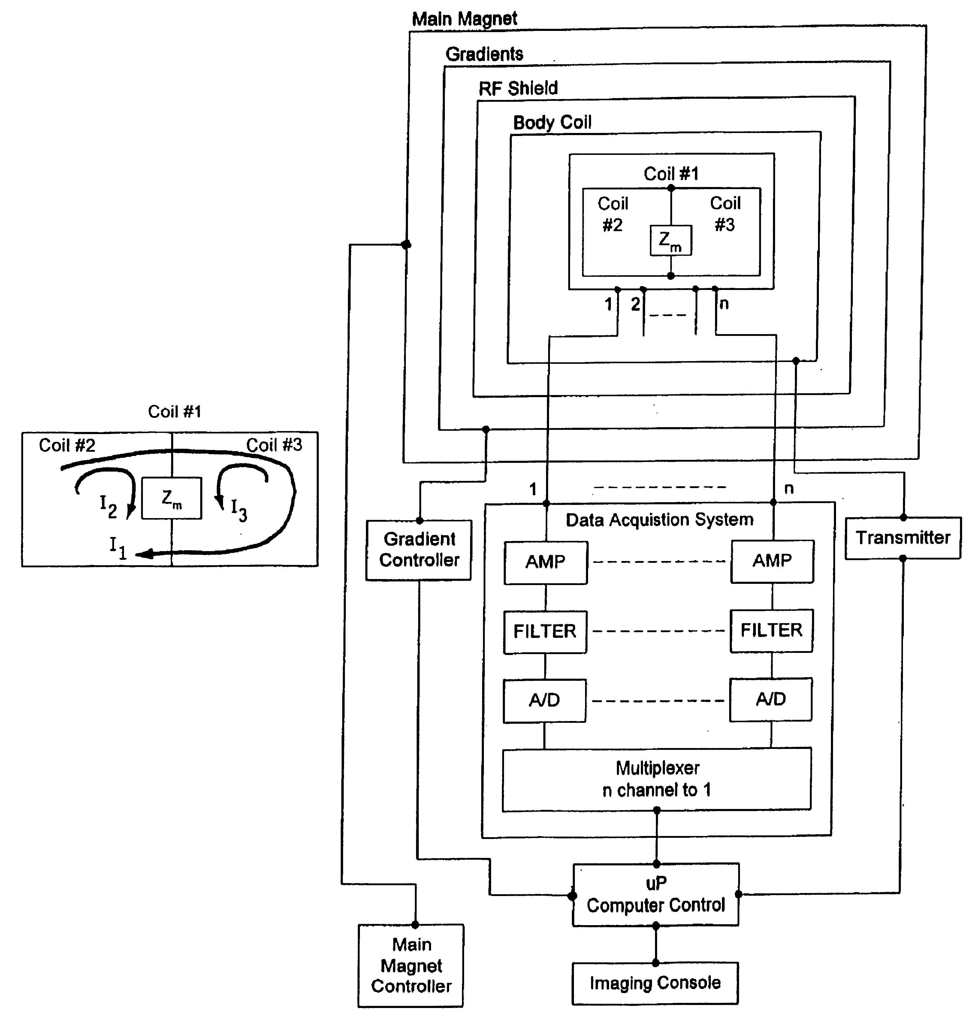
According to one particular aspect of the invention, the provision of more than one coil spanning near identical B fields over the entire FOV is introduced. For example, a larger coil #1 and combined coils #2& #3 span a near identical B field over the imaging FOV. (See, e.g., FIG. 6). In the case of the prior art, the entire FOV is covered by independent RF coils geometrically isolated from one another and arranged in a sequential fashion. In the present invention, two smaller coils #2& #3 are sequentially arranged, but their effective combined coverage is nearly identical to that of the large coil #1 in the array. Such operation is not achieved by the noted prior art. It is noted that RF coils spanning identical FOVs that are well isolated from one another generally result in enhanced S / N, which is beneficial for imaging.
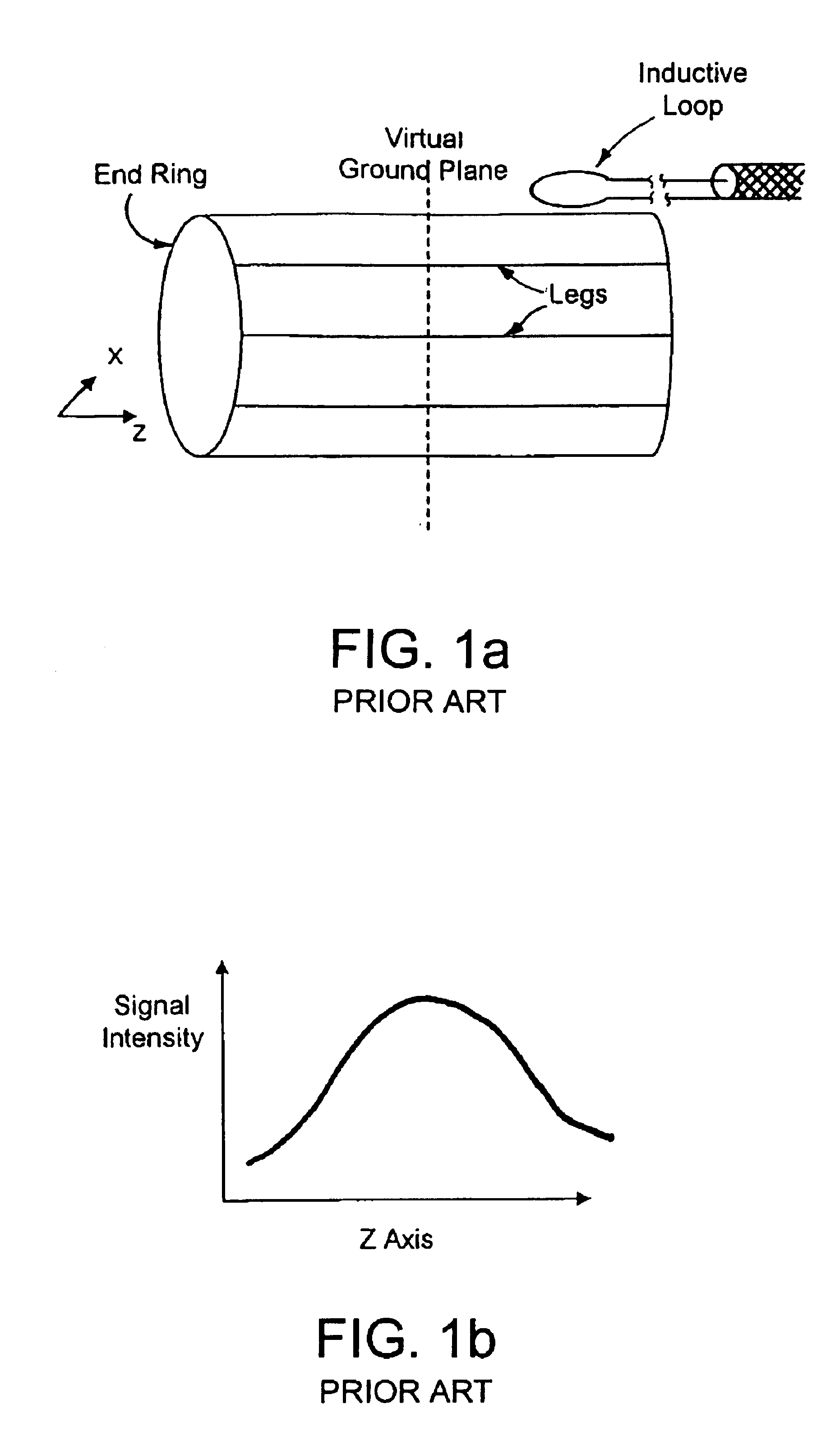
The present invention further relates to the aspect of imaging with both the homogeneous modes and the radio-frequency (RF) gradient mode, more specifically the RF gradient mode oriented along the coil axis is introduced. Several advantages are realized, for example: a) additional S / N along the coil axis away from the coil center; b) more uniform B field along coil axis; c) shorter coil with enhanced S / N without significantly compromising the B field uniformity when compared to the conventional counterpart; d) steeper rolling off of the B field along the coil axis toward the coil ends, which helps maintain a crisp or sharp FOV coverage over the anatomy. As a particular example, signal contributions from the lower neck, upper chest and shoulders are not sought while scanning the human brain. In such case, a coil with rapid fall off is best suited, so unwanted signal artifacts from the neighboring anatomies can be virtually eliminated.
Additionally, the present invention relates to the aspect of isolating coils relatively easily between a set of volume coils. Maintaining good isolation between coils (to less than −20 dB) will maximize combined S / N. Further, the use of an integrated structure will ease the manufacturing process as this will obviate the need for precise geometric positioning needed to cancel the net mutual flux between coils which to-date remains an arduous process.

Problems solved by technology

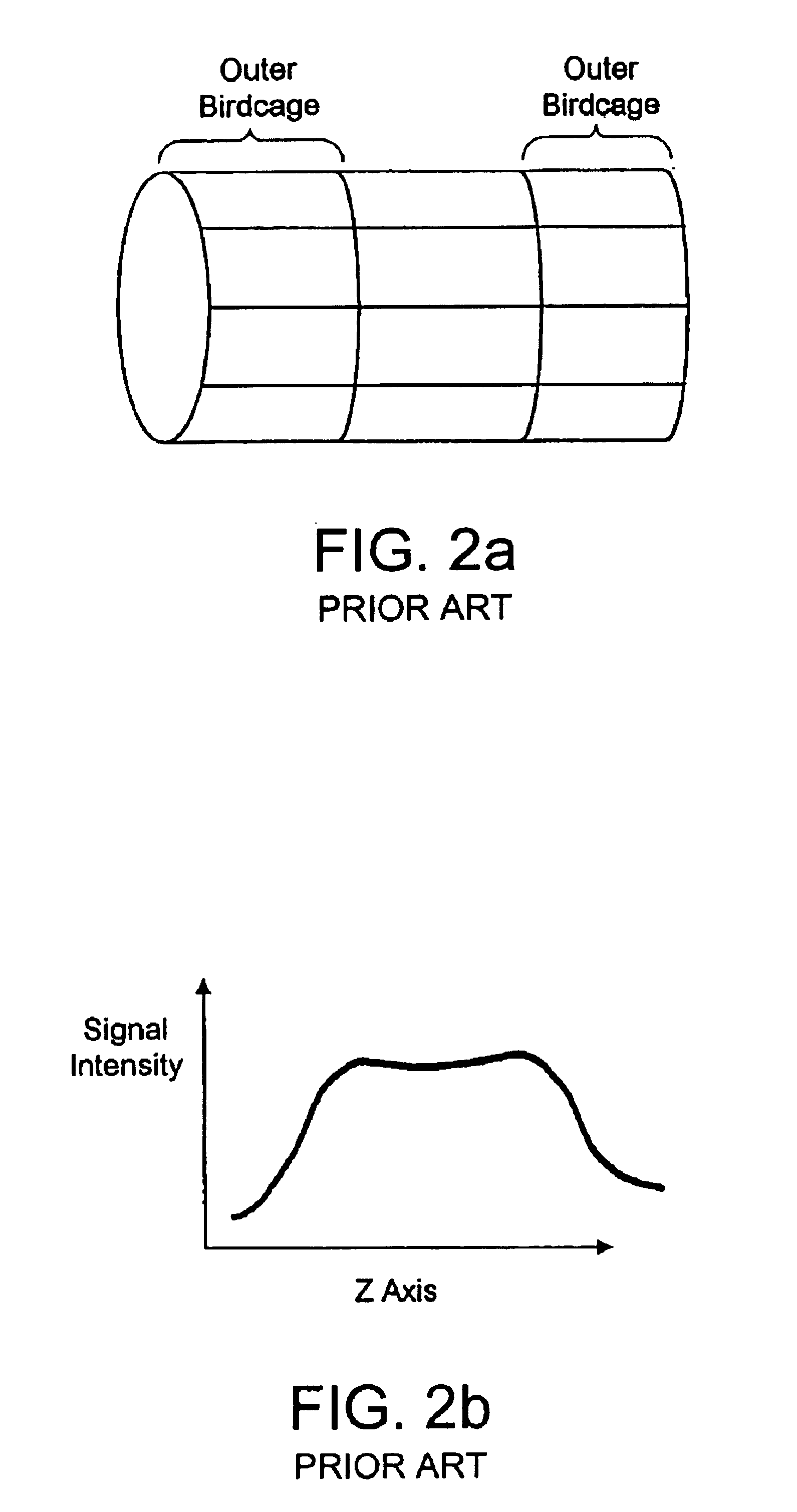
In addition, canceling the coupling between the co-linear modes in the neighboring birdcages in this fashion, does not satisfy the critical coupling for orthogonal modes in neighboring coils.
Misic utilized a complicated design scheme, which was cumbersome to optimize individual coils in the array (mode tuning, matching, alignment and isolation) which in turn made manufacturing an arduous process.

Method used


Image

  • Radio-frequency coil array for resonance imaging analysis
  • Radio-frequency coil array for resonance imaging analysis
  • Radio-frequency coil array for resonance imaging analysis

Examples


second embodiment

A second embodiment is wherein the longer birdcage #1 is driven in the conventional manner using capacitive or inductive coupling (similar to that of FIG. 1a) and the combined coils #2& #3 are driven in the middle, across C3 in ring #3. See FIG. 7a. Driving the combined coil #2& #3 in the above manner generates a RF gradient mode along the coil axis (in this case along the Z axis) which could also be used to image. Note, the Z RF gradient mode is in quadrature. That is, there exists two linear Z RF gradient modes orthogonal to one another.

One such combination of driving the long birdcage with a rectangular loop and the combined coils #2& #3 with a FIG. 8 style loop is shown in FIG. 7b. Again note, two such combinations are needed to drive all four modes of the array (2 homogeneous, 2 RF gradient modes).

From FIG. 7c, the homogeneous mode (of longer birdcage #1) along with the Z RF gradient mode (of the combined birdcages #2, #3) provide a high S / N and highly uniform B field profile a...

third embodiment

With reference to FIG. 8a, two short coils #2& #3 that are electrically connected to one another are driven using inductive coupling loops and their outputs interfaced to separate channels of the receiver system (not shown). Alternatively, capacitive coupling similar to that of Roemer (U.S. Pat. No. 4,887,039) can be used. Note, the two short coils #2& #3 are tuned to the NMR frequency using C1 and C3. The value of C3 is chosen so as to cancel the net mutual coupling between the two stubby birdcages (#2, #3). B field cartoons along the coil axis are shown in FIG. 8b for the individual stubby coils and their combination.

Other Embodiments

Generally, the inventive aspects of FIG. 5 are applicable to all volume coil designs (TEM, solenoid, alderman-grant, counter-rotating coil pair etc.). See for example, FIGS. 13-15, which are extensions of the principles to the solenoid, Alderman-Grant and TEM designs, respectively. Irrespective of the design, the coils in an array can be operated in t...


PUM


Abstract

An RF coil array is provided with increased S / N over the entire imaging FOV. The array design includes a first RF coil spanning the entire FOV, second and third RF coils which together span the entire FOV such that the entire system provides improved S / N over the imaging FOV. An aspect of the invention is the unusual combination of coils in one integrated structure, that are well isolated from one another and maintain preferred current distributions and mode orientations.

Description

TECHNICAL FIELDThe present invention relates to resonance systems, such as magnetic resonance imaging (MRI), nuclear quadrupole resonance (NQR), electron spin resonance (ESR) systems. More particularly, the present invention relates to a radio-frequency (RF) coil array and method for use in such systems. This application is based on provisional application No. 60 / 167,498, filed Nov. 24, 1999, the entire disclosure of which is incorporated herein by reference.BACKGROUND OF THE INVENTIONNMR or MRIIn MRI systems or nuclear magnetic resonance (NMR) systems, a static magnetic field B0 is applied to the body under investigation to define an equilibrium axis of magnetic alignment in the region of the body under investigation. An RF field is applied in the region being examined in a direction orthogonal to the static field direction, to excite magnetic resonance in the region, and resulting RF signals are detected and processed. Generally, the resulting RF signals are detected by RF coil ar...

Claims


Application Information

Patent Timeline
Patent Type & Authority Patents(United States)
IPC IPC(8): G01R33/34
CPCG01R33/34046
Inventor SRINIVASAN, RAVI
Owner ADVANCED IMAGING
Why Eureka
Try Eureka