Method and system for detecting degradation of EGR flow delivery

a technology of egr flow and degradation, applied in the direction of liquid/fluent solid measurement, machines/engines, process and machine control, etc., can solve the problems of requiring the valve itself to have minimal variability in its manufactured flow characteristics, the cost of the map sensor offsets much of the cost benefit of the open loop system, and the deformation of the open loop flow prediction. to achieve the effect of improving fuel economy and reducing engine emissions

Active Publication Date: 2005-02-01
FORD GLOBAL TECH LLC
View PDF13 Cites 30 Cited by
  • Summary
  • Abstract
  • Description
  • Claims
  • Application Information

AI Technical Summary

Benefits of technology

As is known in the art, exhaust gas recirculation (EGR) systems are employed in automotive vehicles in order to help reduce engine emissions and improve fuel economy. Such systems typically employ an EGR valve that is disposed between the engine exhaust manifold and the engine intake manifold, and operable, when in an open position, to recirculate a portion of the exhaust gases from the exhaust side of the engine back to the intake side. In one arrangement, the EGR flow rate to the intake manifold is varied according to one or more sensed condit

Problems solved by technology

The cost of the MAP sensor offsets much of the cost benefit of the open loop system.
Unfortunately, open loop flow prediction degrades rapidly as particulates clog the valve, and requires the valve itself to have minimal variability in its manufactured flow characteristics.
However, this system is slower in reaching its final position.
Furthermore, if used too aggressively to minimize

Method used


Image

  • Method and system for detecting degradation of EGR flow delivery
  • Method and system for detecting degradation of EGR flow delivery
  • Method and system for detecting degradation of EGR flow delivery

Examples


Embodiment Construction

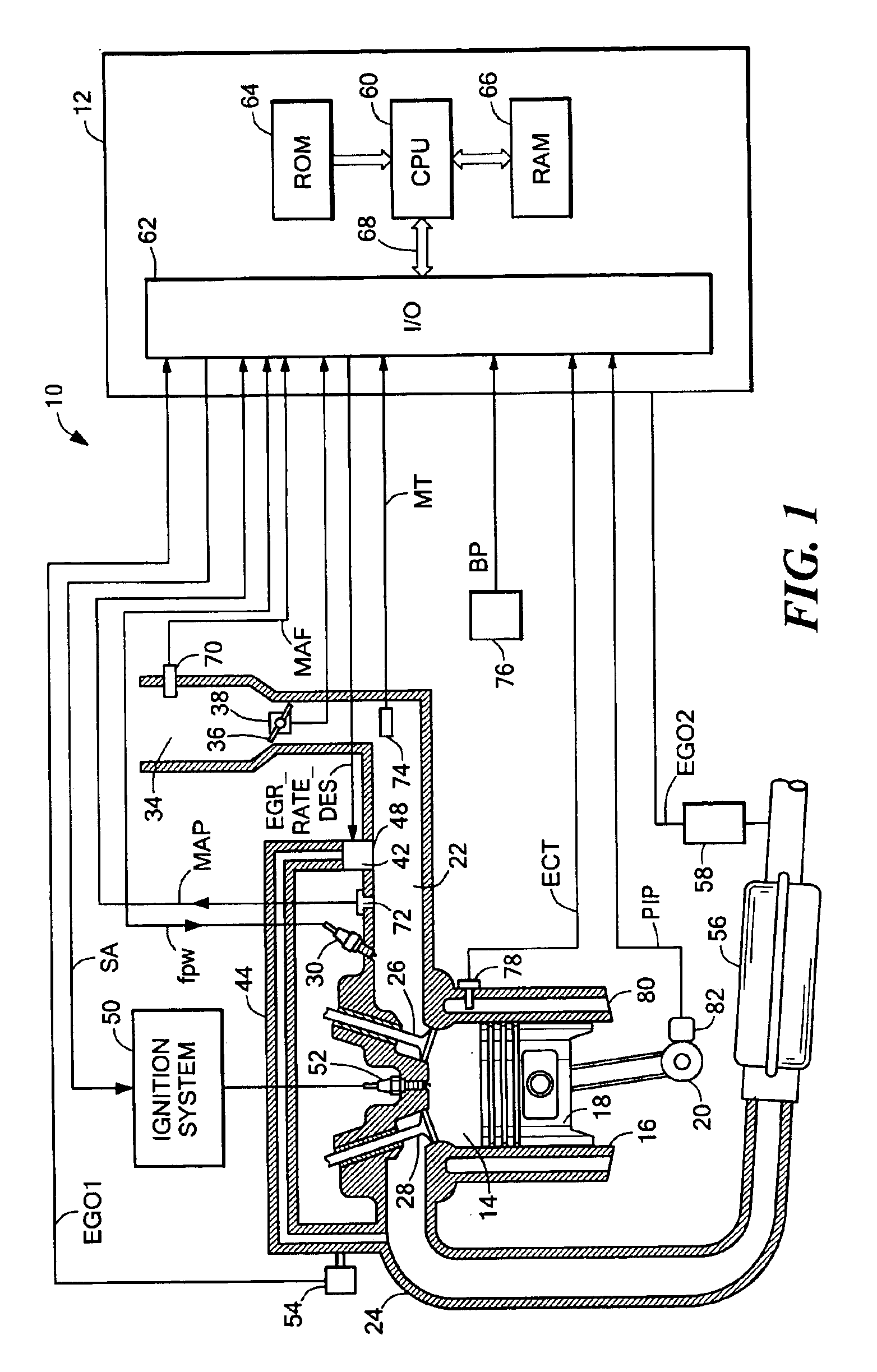
Referring now to FIG. 1, an internal combustion engine 10 is shown having a plurality of cylinders, one cylinder of which is shown in FIG. 1, controlled by electronic engine controller 12. Engine 10 includes combustion chamber 14 and cylinder walls 16 with piston 18 positioned therein and connected to crankshaft 20. Combustion chamber 14 is shown communicating with intake manifold 22 and exhaust manifold 24 via respective intake valve 26 and exhaust valve 28. Intake manifold 22 is also shown having fuel injector 30 coupled thereto for delivering liquid fuel in proportion to the pulse width of signal FPW from controller 12. Both fuel quantity, controlled by signal FPW and injection timing are adjustable. Fuel is delivered to fuel injector 30 by a conventional fuel system (not shown) including a fuel tank, fuel pump, and fuel rail. Alternatively, the engine may be configured such that the fuel is injected directly into the cylinder of the engine, which is known to those skilled in the...


PUM


Abstract

A method for determining EGR flow in an internal combustion engine, such flow being from an exhaust manifold of the engine to an intake manifold of the engine through an EGR valve. The method includes using information provided by a mass air flow sensor disposed upstream of an exhaust gas inlet to the intake manifold and information provided by an manifold absolute pressure sensor disposed downstream of such exhaust gas inlet to provide an indication of the flow of exhaust gas into the intake manifold through such inlet. The method compares such estimated exhaust gas flow into the intake manifold with a commanded exhaust gas flow to the EGR valve. With such method, a determination may be made as to whether the EGR valve is operating properly.

Description

TECHNICAL FIELDThis invention relates generally to methods and systems for detecting degradation of EGR flow delivery.BACKGROUND AND SUMMARYAs is known in the art, exhaust gas recirculation (EGR) systems are employed in automotive vehicles in order to help reduce engine emissions and improve fuel economy. Such systems typically employ an EGR valve that is disposed between the engine exhaust manifold and the engine intake manifold, and operable, when in an open position, to recirculate a portion of the exhaust gases from the exhaust side of the engine back to the intake side. In one arrangement, the EGR flow rate to the intake manifold is varied according to one or more sensed conditions, such as engine temperature, air charge entering the intake manifold, and engine speed. In one type of EGR control system, electrically actuated EGR valves have also been introduced which use software-implemented control logic. Such control logic controls input to an electric actuator motor which, in...

Claims


Application Information

Patent Timeline
IPC IPC(8): F02D21/00F02D41/18F02D41/22F02D41/00F02D21/08F02M25/07G01F1/34G01F1/76G01F9/00G01F15/00
CPCF02D41/0072F02D41/18F02M25/0702G01F1/76G01F9/001G01F15/005G01F1/34F02D2200/0406Y02T10/47F02M26/49Y02T10/40
Inventor YU, SONGPINGCULLEN, MICHAEL J.DANHOFF, GARY LEEJENTZ, ROBERT R.
Owner FORD GLOBAL TECH LLC
Why Eureka
Try Eureka