System and method for determining the required decoupling capacitors for a power distribution system using an improved capacitor model

a power distribution system and capacitor model technology, applied in adaptive control, process and machine control, instruments, etc., can solve the problems of insufficient high frequency, large target impedance requirements, and inability to design power distribution systems that can deliver a large amount of current at a low voltage, so as to achieve more accurate prediction of anti-resonant peaks and facilitate management.

Inactive Publication Date: 2005-02-01
ORACLE INT CORP
View PDF3 Cites 16 Cited by
  • Summary
  • Abstract
  • Description
  • Claims
  • Application Information

AI Technical Summary

Benefits of technology

Thus, in various embodiments, the system and method described herein may allow for improved designs of power distribution systems. Use of the improved capacitor model based on a ladder circuit may allow for more accurate prediction of anti-resonant peaks that may occur at various frequencies during operation of the power distribution system. Accurate prediction of both the frequency and magnitude of the anti-resonant peaks may make these peaks easier to manage in power distribution system designs, and may further help minimize the actual quantity of capacitors necessary to meet target impedance requirements throughout the frequency range of interest.

Problems solved by technology

Designing power distribution systems that can deliver a large amount of current at a low voltage is a significant challenge.
The lower operating voltages may result in much lower target impedance requirements.
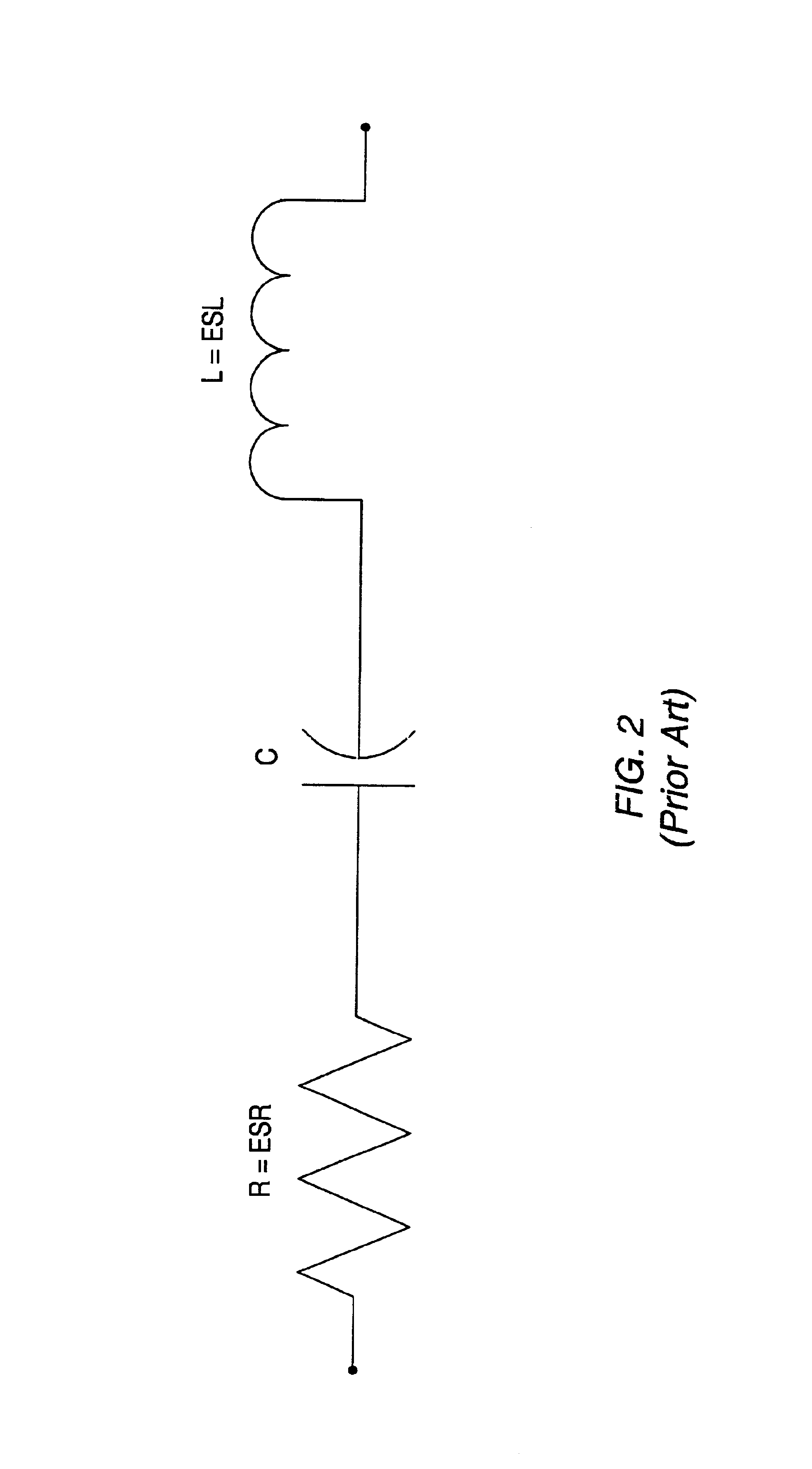
The capacitor model of FIG. 2 may be useful for simulation at lower frequencies, but may be inadequate for higher frequencies.
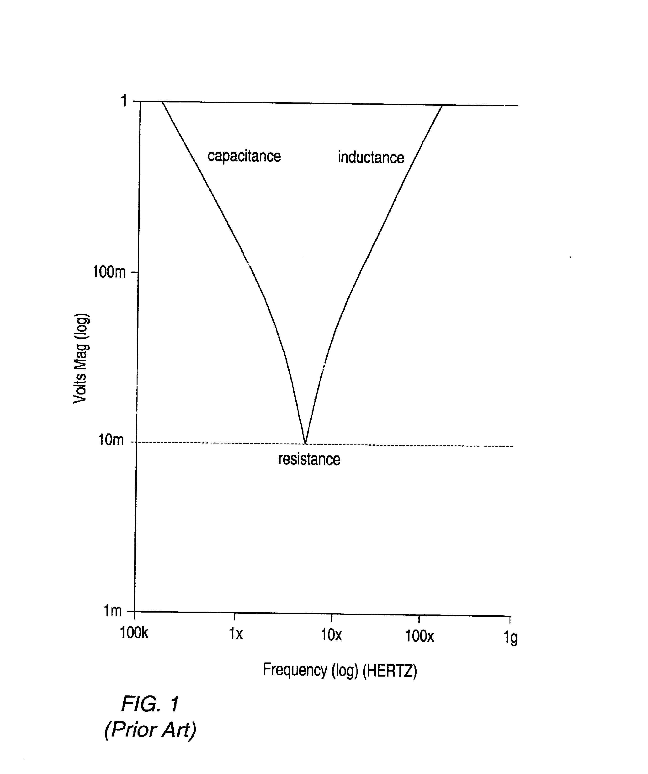
The traditional series RLC circuit model of a capacitor may be unable to correctly predict the frequency or frequencies at which anti-resonances occur.
The higher operating speeds of the various silicon chips in computer systems (or other electronic systems) often times results in the need for higher clock frequencies on system boards.
As such, the traditional RLC series circuit model for capacitors is no longer adequate for determining the necessary decoupling capacitors for a power distribution system.

Method used


Image

  • System and method for determining the required decoupling capacitors for a power distribution system using an improved capacitor model
  • System and method for determining the required decoupling capacitors for a power distribution system using an improved capacitor model
  • System and method for determining the required decoupling capacitors for a power distribution system using an improved capacitor model

Examples


Embodiment Construction

FIG. 4—Power Distribution System Model

FIG. 4A is a top view of a simplified schematic of one embodiment of a model of a power distribution system for an electronic circuit. As shown, the model comprises a grid 300A of transmission line segments. The segments are grouped into unit cells 350. As shown, there are eight columns labeled “a” through “h”, as well as eight rows labeled, from the bottom to the top, “1” through “8”. The model preferably comprises a SPICE array of transmission lines in a fixed topology (i.e. in an 8×8grid). The transmission lines may be of variable lengths such that the fixed topology may be used on electrical connecting device of any physical dimensions. It is noted that other embodiments of the power distribution system are contemplated, such as an elliptical model based on a “wheel and spoke” geometry. The model may be implemented using circuit simulation software on a computer system. In one embodiment, the model may be a SPICE model, although models using...


PUM


Abstract

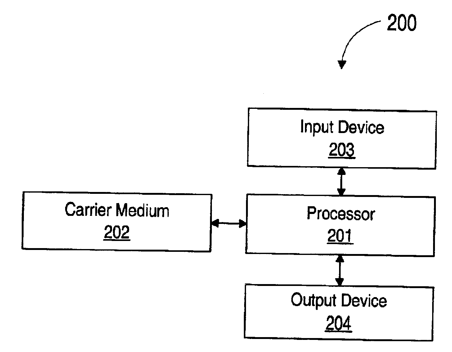
A system and method for determining the required decoupling capacitors for a power distribution system using an improved capacitor model. In one embodiment, a method for determining the decoupling capacitors for a power distribution system includes creating a model of the power distribution system using circuit simulation software, such as SPICE. The power distribution system model includes a plurality of cells interconnected at predetermined nodes. The method then selects one or more decoupling capacitors for the power distribution system. The decoupling capacitors are represented in the power distribution system model by a capacitor model, which is a mathematical model of an electrical circuit. The electrical circuit upon which the capacitor model is based is a ladder circuit. Following the selecting of the decoupling capacitors, the power distribution system model is update based on the selections, and operation of the power distribution system is then simulated. During the simulation, transfer impedance values are determined for each of the nodes, and compared to target impedance. The method is then repeated until each of the transfer impedance values is at or below the target impedance.

Description

BACKGROUND OF THE INVENTION1. Field of the InventionThis invention relates to electronic circuits, and more particularly, the design of power distribution systems.2. Description of the Related ArtAs computer systems advance, there is a continuous demand for systems which demand higher power at a relatively low voltage. Designing power distribution systems that can deliver a large amount of current at a low voltage is a significant challenge. Tight voltage tolerances (e.g. ±5%) are often times required to ensure the proper performance of silicon chips within a computer system. The lower operating voltages may result in much lower target impedance requirements. At the same time, the clock frequencies for microprocessors and other types of silicon chips is continually increasing, thereby resulting in a much wider frequency range for which target impedance requirements must be met.Power distributions systems typically include at least one pair of planar conductors (e.g. a power plane an...

Claims


Application Information

Patent Timeline
Patent Type & Authority Patents(United States)
IPC IPC(8): G06F17/50H01P5/12
CPCG06F17/5036G06F30/367
Inventor SMITH, LARRY D.HOCKANSON, DAVID
Owner ORACLE INT CORP
Why Eureka
Try Eureka