Laser welding boiler tube wall panels

Inactive Publication Date: 2005-02-08
THE BABCOCK & WILCOX CO
View PDF19 Cites 16 Cited by
  • Summary
  • Abstract
  • Description
  • Claims
  • Application Information

AI Technical Summary

Benefits of technology

The present invention is possible because lasers now have the capacity to weld in an industrial setting. In one embodiment, the laser is used to replace SAW and GMAW welding provided proper placement and fixation of the panel parts is used. The method advantageously can simultaneously produce a fillet on both sides of the boiler tube wall panel, thereby reducing stress concentration. The method can therefore be used to weld boiler tube wall panels solely from one side of the panel, while still producing a full penetration weld, i.e. a weld that penetrates to the

Problems solved by technology

A laser can also be used to weld areas of a panel that

Method used


Image

  • Laser welding boiler tube wall panels
  • Laser welding boiler tube wall panels
  • Laser welding boiler tube wall panels

Examples


first embodiment

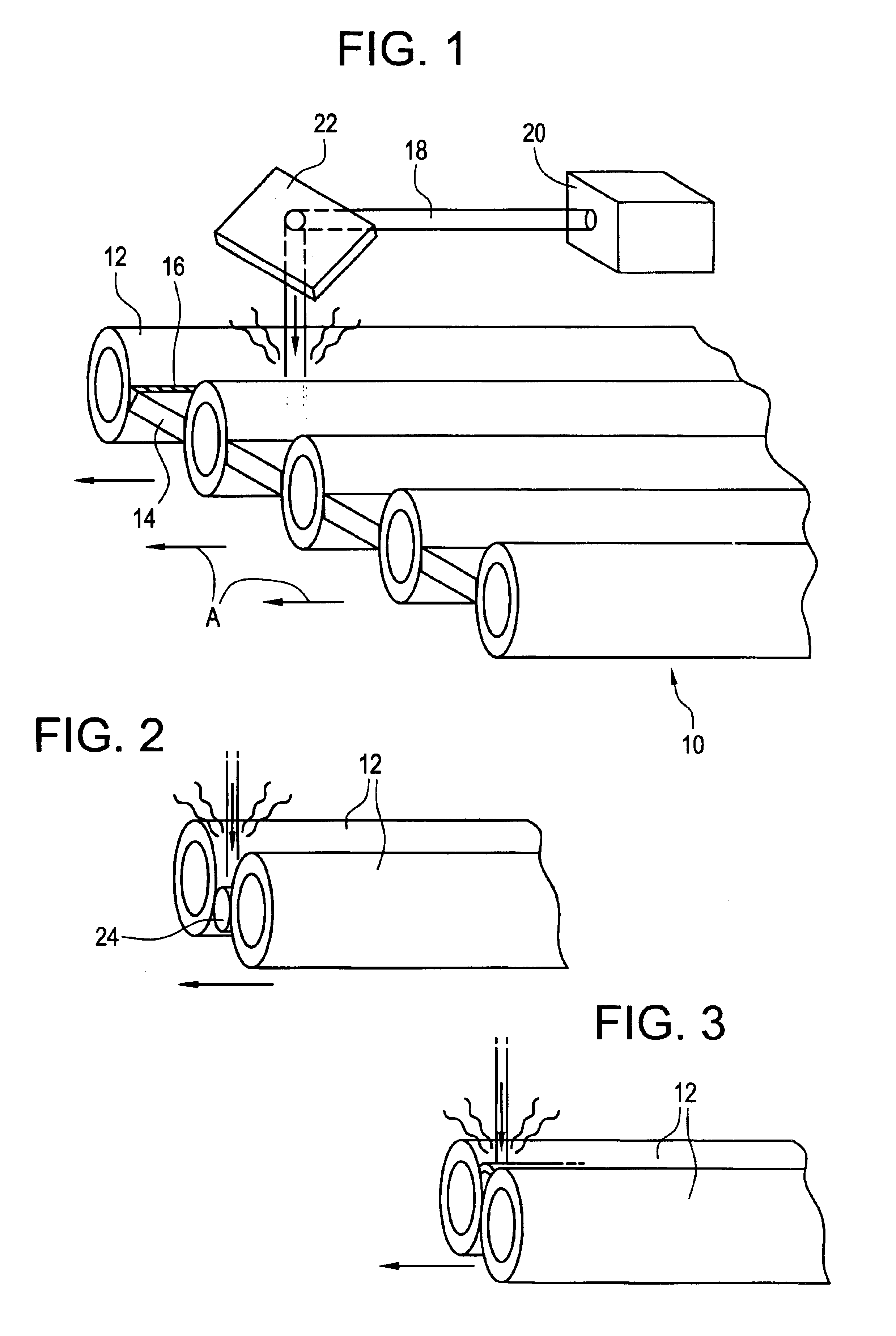
FIG. 5 shows a preferred setup of the invention for the invention in which a laser beam 18 is used to form the weld line 16. According to this embodiment, laser beam 18 is advantageously directed toward the weld line 16 inclined at a laser beam angle 2, measured from a line L1 perpendicular to a plane of the panel and in a plane perpendicular to the weld line 16, within the range of about 2 to 15 degrees, and preferably about 5 to 10 degrees.

In a laboratory test of the above laser-only embodiment membrane plate 14 was successfully welded along weld line 16 to a tube 12 solely from one side of the membrane plate 14, using the following process parameters:

laser travel speed:about 35 inches per minutelaser power:5.5 kW

Laser beam 18 was directed toward the welding point P at a laser beam angle 2 of about 5 degrees. The tube 12 used in the test was a carbon steel tube having an outer diameter of 1.5 inches and a wall thickness of 0.203 inches. The membrane plate 14 was made of A36 steel ...

second embodiment

FIG. 7 shows a preferred setup of the invention for a second embodiment that combines a known GMAW welding head 26 with the laser beam 18 to form the weld line 16. For a fixed laser power, the addition of GMAW welding head 26 makes the method of the present invention more reliable in a production environment.

In the laser-plus-GMAW embodiment laser beam 18 is advantageously directed toward the weld line 16 inclined at the laser beam angle 2, as shown in FIG. 7, within the range of about 2 to 15 degrees, and preferably about 5 to 10 degrees, and the GMA welding axis is directed toward the weld line 16 at a torch angle 4 of about 5 degrees measured from a plane PL perpendicular to the plane of the panel and containing the weld line 16, also as shown in FIG. 7 (or within the range of about 2 to 15 degrees). Further the GMA welding axis is applied at a lead angle 6 relative to the travel direction A within the range of about 10 to 50 degrees or preferably about 20 to 40 degrees.

For purpo...

third embodiment

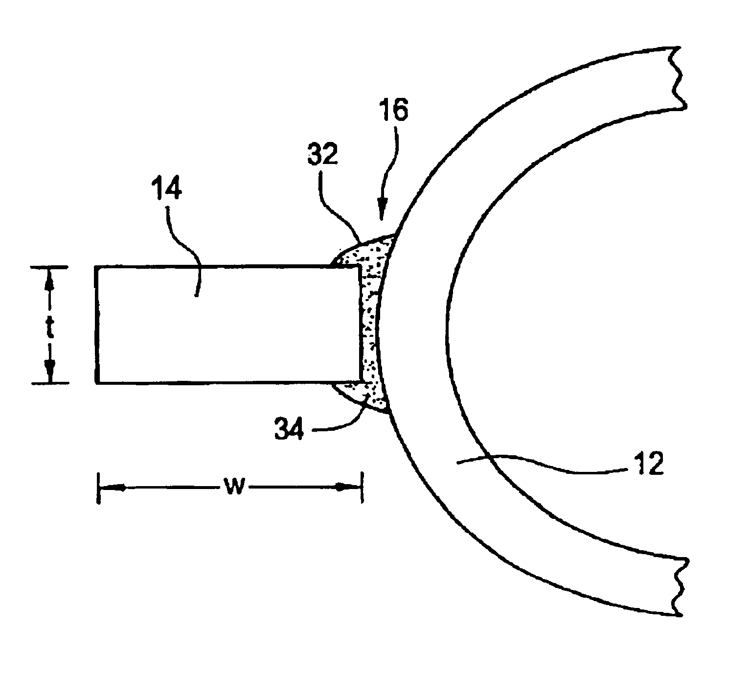
FIG. 8 illustrates a preferred arrangement of the invention in which the membrane plate 14 is modified to include a bevel 30 along the edge adjacent weld line 16. The beveled membrane plate 14′ is beveled at a bevel angle b to a depth d.

In a laboratory test of the laser-plus-GMAW embodiment with a beveled membrane plate 14″, the beveled membrane plate 14′ was successfully welded along weld line 16 to a tube 12 solely from one side of the membrane, using the following process parameters:

laser and GMAW travel speed:about 31 inches per minutelaser power: 5 kWGMAW shield gas:100% heliumGMAW wire:0.035″ dia. ER70S-3GMAW wire feed speed:about 100 inches per minuteGMAW voltage:about 25 voltsGMAW peak current:100 ampsGMAW background current: 30 amps

GMAW welding head 26 was directed toward the welding point P at a torch angle 4 of about 5 degrees and a lead angle 6 of about 32 degrees. Laser beam 18 was directed toward the welding point P at a laser beam angle 2 of about 5 to 10 degrees. The...


PUM

PropertyMeasurementUnit
Lengthaaaaaaaaaa
Fractionaaaaaaaaaa
Thicknessaaaaaaaaaa

Abstract

A method of welding together the parts of a boiler tube wall panel includes placing at least two parts of the panel to be welded together along a weld line and adjacent each other, and forming a weld along the weld line using a laser beam. The method can advantageously be used to weld boiler tube wall panels solely from one side of the panel. A GMAW process can also be used in combination with the laser beam to form the weld. Where the boiler tube wall panel includes a membrane between tubes, the membrane may be beveled.

Description

FIELD AND BACKGROUND OF THE INVENTIONThe present invention relates generally to the field of welding and, in particular, to a new and useful method of welding boiler tube wall panels using lasers.Boiler tube wall panels or membrane panels of all types can be welded by the present invention. Such panels are either welded together, sided-by-side tubes with tangent tube welds therebetween, or tubes alternating with narrow flat plates called membrane bars, or round rods or bars to form a gas-tight wall. The tubes are generally about 1½ to 3 inches OD with wall thicknesses of about 0.15 to 0.30 inches. The thickness of the plates between the tubes is about ¼ to ⅜ and they can be up to about 3 inches wide. The plates are thus zero to 3 inches wide, the zero dimension indicating no plate present, i.e. a tangent tube weld, between adjacent tubes. The rod or round bar is about ⅛ to ½ inches in diameter. Welds needed to assemble such boiler tube wall panel parts must be from about 10 to 60 fe...

Claims


Application Information

Patent Timeline
IPC IPC(8): B23K26/14B23K28/02B23K28/00B23K26/00B23K26/26B23K26/24B23K9/173F22B37/00F22B37/10
CPCB23K9/173B23K26/243B23K26/26B23K26/1429F22B37/102B23K28/02B23K2201/06B23K26/242B23K26/348B23K2101/06
Inventor HARTH, III, GEORGE H.
Owner THE BABCOCK & WILCOX CO
Why Eureka
Try Eureka