Robot controller

a robot controller and controller technology, applied in the field of robot controllers, can solve the problems of reducing affecting the safety of workers, and requiring a large amount of time and labor, so as to shorten the time for correcting work programs, improve the efficiency of robot teaching work, and reduce the risk of accidents

Inactive Publication Date: 2005-02-08
YASKAWA DENKI KK
View PDF14 Cites 124 Cited by
  • Summary
  • Abstract
  • Description
  • Claims
  • Application Information

AI Technical Summary

Benefits of technology

Therefore, it is a primary object of the invention to provide a robot controller having features, which comprise high efficiency of robot teaching work, shortening of the time in correcting work programs, lightening of work load, and an increase in s

Problems solved by technology

However, where a series of work programs include several tens through several hundreds of work points, it is difficult to recognize sections where the robot actually operates, by only checking the movement section and work section in the programs written in terms of a robot language.
Therefore, a great amount of time and labor are required.
Also, since it is necessary to operate the key many times and attention must be paid to avoid obstacles, there arises a danger that may be brought about due to a lack of attention in the movements of the robot.
However, in the prior art method for confirming descriptions of work programs, since the work programs are written in terms of movement commands and work commands, which are inherent to a robot control

Method used


Image

  • Robot controller
  • Robot controller
  • Robot controller

Examples


embodiment 1

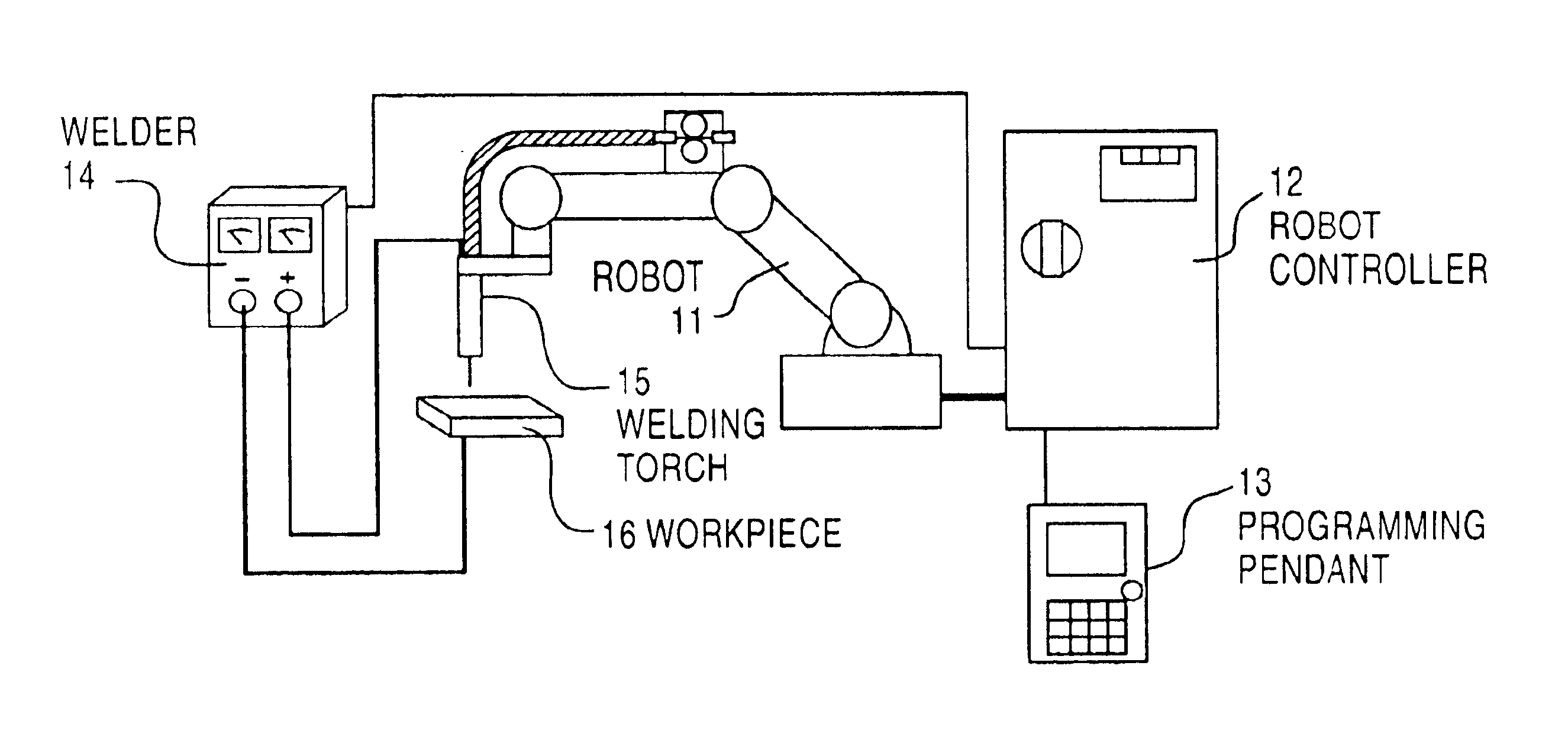
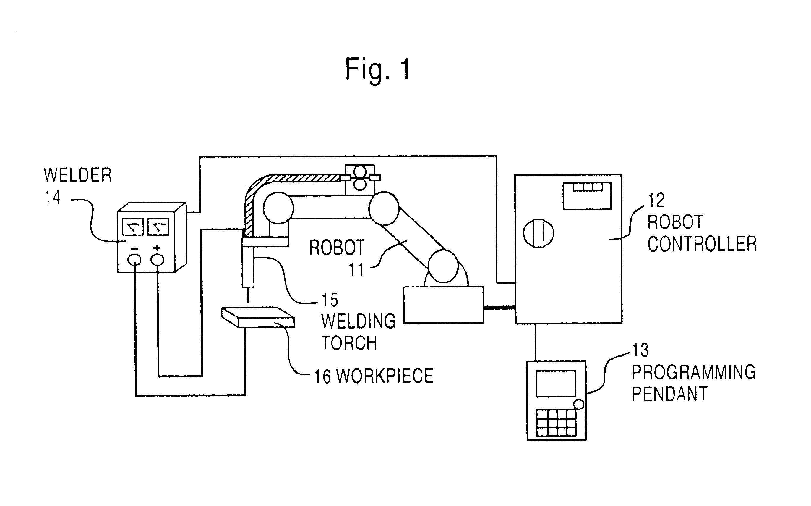
FIG. 1 is a configurational view of a welding robot system according to the invention. A robot 11 operates by commands from a robot controller 12.

A programming pendant 13 is a human interface for displaying, preparing and editing states of a robot and work programs. When teaching the robot work, an operator prepares and edits work programs while operating the robot 11 and robot controller 12 by operating the programming pendant 13.

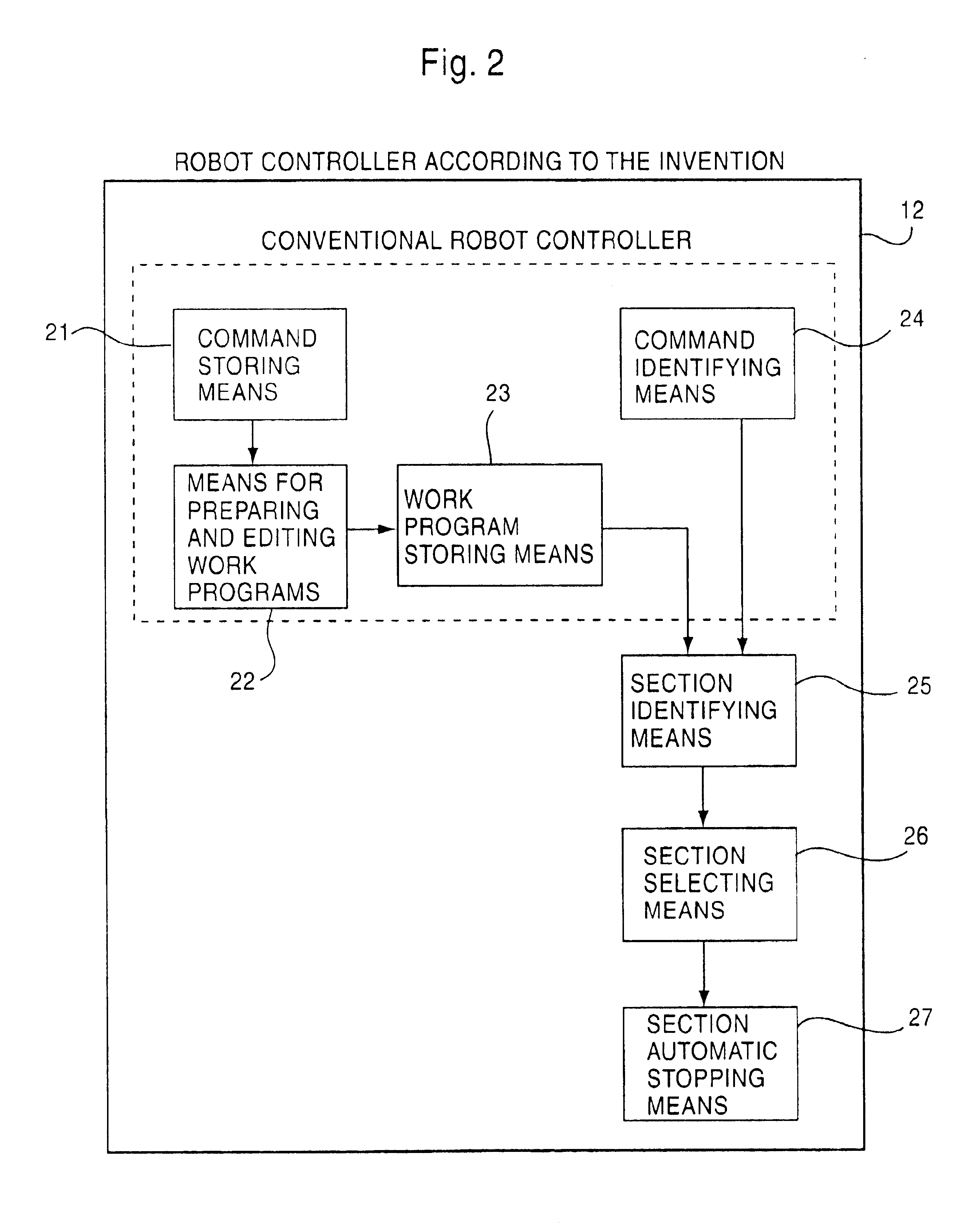
When a work program is completed and the robot 11 is caused to carry out work, the robot controller 12 actuates the robot 11 as a work program, and at the same time, outputs a command to a welder 14. The welder 14 issues outputs (current and voltage) suited to a command to a welding torch 15 and a workpiece 16 to be welded, and welding is carried out. FIG. 2 is a block diagram showing a construction of the invention. The robot controller according to the invention is comprised of command storing means 21, means 22 for preparing and editing work programs, w...

embodiment 2

Next, a detailed description is given of the second embodiment regarding a movement method to correction positions of Step 34 and Step 37 in FIG. 3 with reference to a view showing a work program example in FIG. 7 while comparing a prior art movement method in FIG. 8 with a movement method according to the invention in FIG. 9. FIG. 7 showing a work program example is composed of a movement command and a work command.

Circle marks shown in FIG. 8 and FIG. 9 indicate the tip end positions of a welding torch 15, respective fine lines therein indicate air-cut sections, respective thick lines therein indicate work sections (welding sections) in which work is carried out while moving, a double line therein indicates a section to be corrected, and an arrow indicates a movement section in which a robot moves by pressing the operation key of the teaching pendant 13 once.

In addition, figures attached to respective lines in FIG. 8 and FIG. 9 indicate command numbers attached to the left side in...

embodiment 3

Hereinafter, a description is given of a mode of the invention while taking a welding work as an example, with reference to the drawings.

FIG. 10 is a configurational view of a welding robot system according to the invention. The robot 11 moves by commands from the robot controller 12. In a welding work section, a command signal is transmitted from the robot controller 12 to a welder 14, and welding is carried out under appointed conditions. Also, work information such as various types of work conditions regarding work programs, work movement information and robot loci is displayed on a display unit 30, wherein it is possible to instantaneously check the work contents of respective work programs. The work information is outputted to a peripheral memory unit 31 such as a personal computer via a communications interface, wherein it is possible to check the work management information. A peripheral work state monitoring unit 32 is a unit that detects a current and a voltage during weldi...


PUM

PropertyMeasurementUnit
Efficiencyaaaaaaaaaa

Abstract

A robot controller for teaching a robot with high efficiency. The robot controller including command storage unit (21) where a movement command and a work command are stored, command identifying unit (24) for discriminating between the movement and work commands, unit (22) for making/editing a series of work programs or discrete work programs by a combination of the commands, work program storage units (23) where the work programs are stored so as to control the robot according to the stored program, further including a work section identifying unit (25) for identifying a work section of the work program by way of the command identification unit (24) and work section automatic stopping unit (27) for automatically stopping or suspending the execution of the work program at the work section in a standby state when the work section identifying unit (25) identifies the work section during the execution of the work program.

Description

TECHNICAL FILEDThe present invention relates to a robot controller based on a teaching and playback system.BACKGROUND ARTAt present, various robots have been put into practice in various fields and are in operation. Almost all the robots are based on a teaching and playback system. In order to cause the robots to carry out movements and commands, it is necessary for a robot operator to prepare work programs by teaching work. Various types of movement commands and work commands are described in the work programs. By selecting and carrying out the work programs after the work programs are prepared, a robot executes a series of movements and works per teaching.The teaching method of a robot, which is disclosed in Japanese Laid-Open Patent Publication No. Hei-8-19975 stores teaching data with identification numbers attached per work section, wherein editing of a sequence of a work section is enabled.However, in order to modify the position / posture of a robot, movement conditions and wor...

Claims


Application Information

Patent Timeline
IPC IPC(8): B23K9/12B25J9/16G05B19/00G05B19/425G05B19/4155B25J9/22
CPCB23K9/126B25J9/1656G05B19/425G05B19/00G05B2219/40387G05B2219/36045G05B19/42
Inventor HIRAYAMA, TAKAHIDEOKUMURA, SHINJIHANDA, HIYOYUKIOKAMOTO, TAKESHI
Owner YASKAWA DENKI KK
Why Eureka
Try Eureka