
Rolling element for a continuously variable transmission (CVT), a CVT using the rolling element and a method for producing the rolling element

a technology of continuously variable transmission and rolling element, which is applied in the field of rolling element, can solve the problems of deteriorating rolling contact fatigue life of the races, flaking or peeling, etc., and achieve the effects of improving the volumetric capacity of the cvt, reducing the dimension thereof, and improving the fatigue strength of the rolling contact portions

Inactive Publication Date: 2005-02-22
NISSAN MOTOR CO LTD
View PDF13 Cites 2 Cited by
  • Summary
  • Abstract
  • Description
  • Claims
  • Application Information

AI Technical Summary

Benefits of technology

[0008]For the purpose of increasing volumetric capacity of the CVTs or reducing dimension thereof, there is a demand to improve rolling contact fatigue strength of rolling contact portions of a rolling element for the CVTs, such as the input and output disks and the power rollers of the toroidal CVT, by increasing hardness or resistance to crack in outer layers of the rolling contact portions.
[0009]An object of the present invention is to provide a rolling element for a continuously variable transmission (CVT) which is improved in rolling contact fatigue life, a CVT using the rolling element, and a method for producing the rolling element.

Problems solved by technology

The internal microstructural change is caused by foreign materials intervening between the traction surfaces of the disks and the power rollers and between the bearing surfaces of the races of the power rollers and the balls, or caused by rolling contact fatigue due to the rolling contact between the traction surfaces and between the bearing surfaces and the balls.
Cracks will occur at the depth position in the traction surfaces of the races and the disks and the bearing surfaces of the races, which grow up to outer layers of the traction surfaces and the bearing surfaces to cause flaking or peeling thereof.
Further, when the balls roll on the bearing surfaces of the races of the power rollers, not only the high contact surface pressure but traction force and radial load are applied onto the bearing surfaces.
As a result, rolling contact fatigue lives of the races will be deteriorated.

Method used


Image

  • Rolling element for a continuously variable transmission (CVT), a CVT using the rolling element and a method for producing the rolling element
  • Rolling element for a continuously variable transmission (CVT), a CVT using the rolling element and a method for producing the rolling element
  • Rolling element for a continuously variable transmission (CVT), a CVT using the rolling element and a method for producing the rolling element

Examples


examples

[0047]The present invention is described in more detail by way of examples and comparative examples by referring to the accompanying drawings. However, these examples are only illustrative and not intended to limit a scope of the present invention thereto. In the following examples and comparative examples, a surface microhardness, a surface Vickers hardness and a rolling contact fatigue life were measured and evaluated by the following method.

Evaluation of Surface Microhardness

[0048]Hardness distribution in an outer surface layer of a specimen in a depth direction thereof was measured using a microvickers hardness tester (Full Automatic Microvickers Hardness Tester MF-IV2000, manufactured by NIPPON STEEL CO.). A load of 10 g was applied to an indenter of the microvickers hardness tester. The value measured at a depth of 5 μm from the outer-most surface of the outer surface layer was determined as the surface microhardness.

Evaluation of Surface Vickers Hardness

[0049]Hardness distrib...

examples 1-7

[0051]The specimen was prepared in the following manner. The specimen as a workpiece was made of steel for machine structural use which had a chemical composition shown in Table 1.

TABLE 1SteelSampleChemical Composition (mass %)No.CSiMnCrNiMoVA320.21.00.32.02.00.70.2

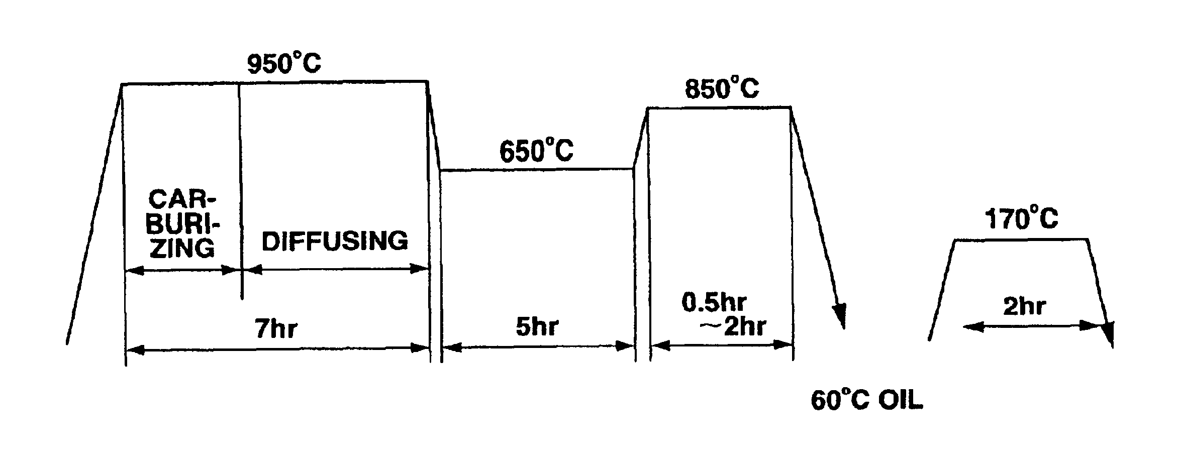
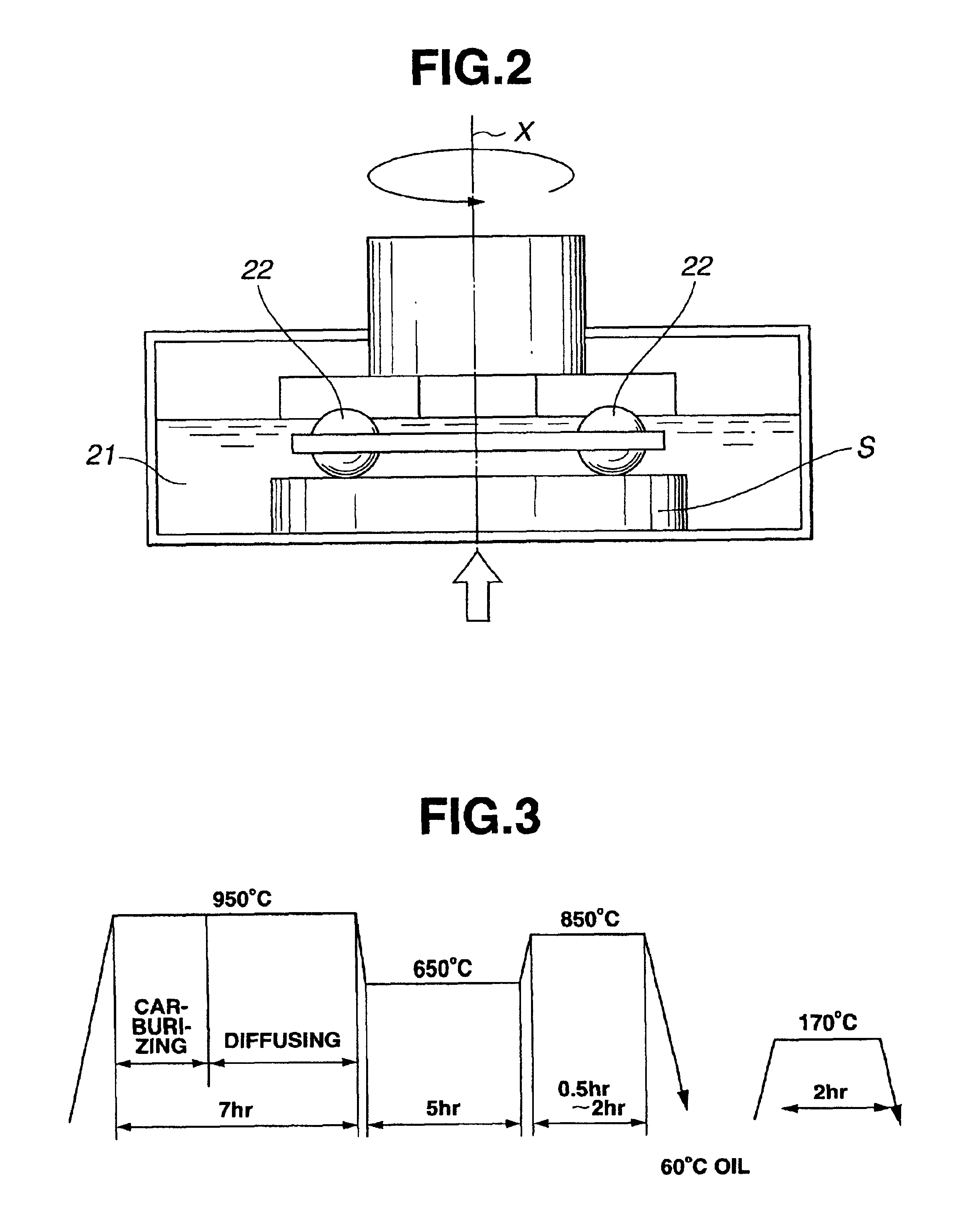
[0052]The specimen was subjected to rough machining and heat treatment shown in FIG. 3, to provide a hardened outer surface layer. The specimen was subjected to carburizing, quenching and tempering under the heat treatment conditions shown in FIG. 3. The carburizing was carried out using a plasma furnace. In Examples 1-7, the ratio between carburizing time and diffusing time, and keeping time at 850° C. were appropriately adjusted so as to control a surface hardness and a surface residual austenite content in the outer surface layer of the specimen. Subsequently, the specimen was subjected to grinding with a machining allowance of 0.2 mm. The machining allowance was determined so as to completely eliminate a surface abnor...

example 8

[0059]The specimen was prepared in the same manner as described in Examples 1-7, except that the specimen was not subjected to grinding before shot peening. The specimen before and after shot peening was subjected to the same evaluations of the properties as described in Examples 1-7. The rolling contact fatigue life test was carried out to calculate the L50 life and the Weibull coefficient in the same manner as described in Examples 1-7. The results of the evaluations and the calculations were shown in Table 2.


PUM

PropertyMeasurementUnit
Pressureaaaaaaaaaa
Percent by massaaaaaaaaaa

Abstract

A rolling element for a continuously variable transmission, including a plurality of rolling members having rolling contact portions that come into rolling contact with each other via lubricating oil. At least one of the rolling contact portions includes an outer surface layer having a surface microhardness of not less than Hv 750, a surface residual compressive stress of not less than 1000 MPa and a residual austenite content of not more than 10% by volume.

Description

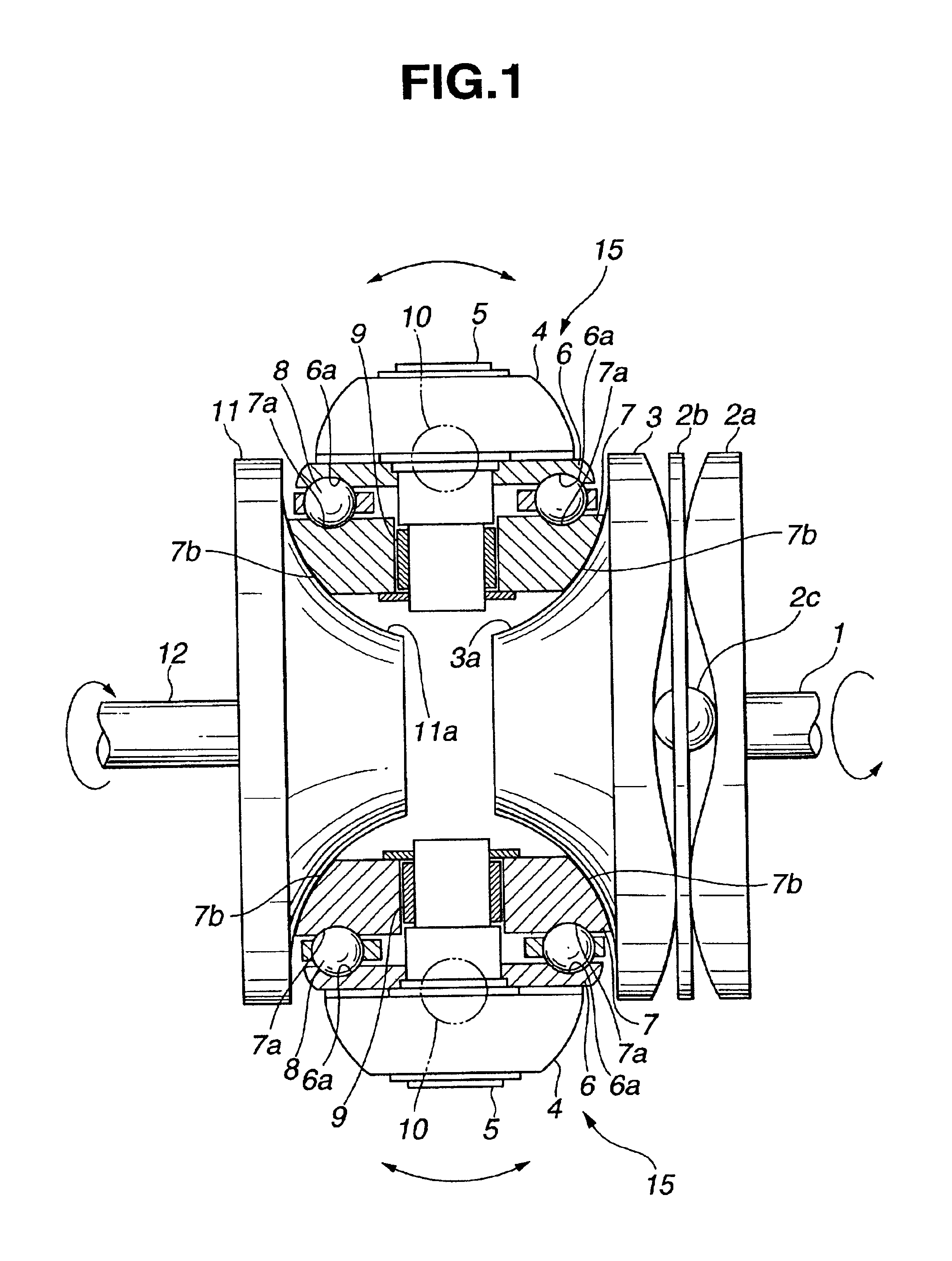
BACKGROUND OF THE INVENTION[0002]The present invention relates to a rolling element for use in a continuously variable transmission (CVT), such as a toroidal CVT, for automobiles. More specifically, this invention relates to the rolling element for the CVT which is improved in rolling contact fatigue life, and a method for producing the rolling element.[0003]The toroidal CVT includes an input disk, an output disk and power rollers interposed between the input and output disks. Each of the power rollers includes inner and outer races and a plurality of balls between the races. The races have bearing surfaces contacted with the balls via lubricating oil. The inner race of the power roller has a traction surface contacted with a traction surface of each of the disks via lubricating oil. Rotation of the input disk is transmitted to the output disk by the traction drive produced between the traction surfaces of the disks and the traction surfaces of the power rollers.[0004]U.S. Pat. No. ...

Claims


Application Information

Patent Timeline
IPC IPC(8): F16H15/32F16H15/38F16H15/00C21D1/06C21D7/06B24C1/10C21D9/40C22C38/00C22C38/22C23C8/38C23C8/80
CPCF16H15/38F16H15/00
Inventor KINO, NOBUOUCHIYAMA, NORIKOYAMAGUCHI, TAKUROOTANI, KEIZO
Owner NISSAN MOTOR CO LTD
Learn More