Method and apparatus for rapid change of fluorescence bands in the detection of dyes in fluorescence microscopy

a fluorescence microscopy and dye technology, applied in scanning probe microscopy, spectral investigation, photometry, etc., can solve the problem of inflexible adaptation of detection and excitation to corresponding new dye characteristics for users

Inactive Publication Date: 2005-02-22
CARL ZEISS MICROSCOPY GMBH
View PDF38 Cites 25 Cited by
  • Summary
  • Abstract
  • Description
  • Claims
  • Application Information

AI Technical Summary

Benefits of technology

Therefore, the primary object of the invention is the provision of novel methods for flexible and freely programmable detection. These methods should be usable in image-generating and analytic microscopy systems. The microscope systems are image-generating systems such as laser scanning microscopes for three-dimensional examination of biological preparations wi

Problems solved by technology

With the arrangement described above, it is impossible for the user to flexi

Method used


Image

  • Method and apparatus for rapid change of fluorescence bands in the detection of dyes in fluorescence microscopy
  • Method and apparatus for rapid change of fluorescence bands in the detection of dyes in fluorescence microscopy
  • Method and apparatus for rapid change of fluorescence bands in the detection of dyes in fluorescence microscopy

Examples


embodiment form

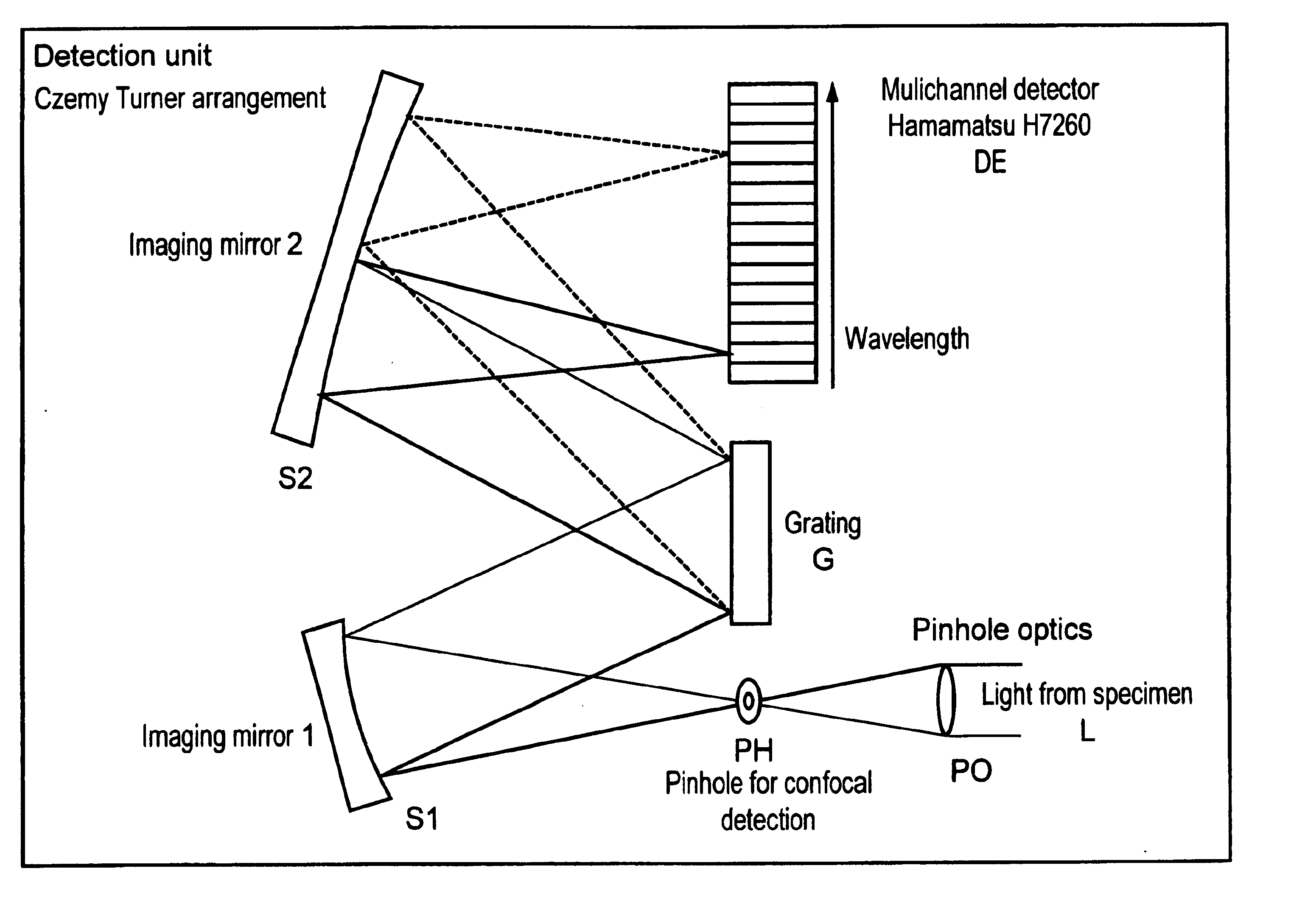
A possible embodiment form of the optical beam path of the detector unit shown in the block diagram in FIG. 5 is shown in FIG. 6. The construction is essentially a Czerny Turner construction. In confocal detection, the light L from the specimen is focused through the confocal diaphragm PH by the pinhole optics PO. With non-descanned detection in case of multiphoton absorption, this diaphragm can be omitted. The first imaging mirror S1 collimates the fluorescent light. Subsequently, the light strikes a line grating G, for example, a grating with a line number of 651 lines per mm. The grating bends the light in different directions corresponding to its wavelength. The second imaging mirror S2 focuses the individual spectrally split wavelength components on the corresponding channels of the line detector DE. The use of a secondary electron multiplier array by Hamamatsu H7260 is especially advantageous. The detector has 32 channels and high sensitivity. The free spectral region of the e...


PUM


Abstract

A method is disclosed for operation of an image-generating optical system for detection of characteristic quantities of the wavelength-dependent behavior of an illuminated specimen, such as the emission behavior and/or absorption behavior and, in particular, the fluorescence and/or luminescence and/or phosphorescence and/or enzyme-active light emission and/or enzyme-active fluorescence, for the operation of a laser scanning microscope, comprising the steps of splitting the image point information of the specimen into spectral components in a spatially resolved manner on the detection side in dependence on wavelength and carrying out at least one summing for different spectral components.

Description

BACKGROUND OF THE INVENTIONa) Field of the InventionThe invention is directed to a method and an arrangement in fluorescence microscopy, particularly laser scanning microscopy, fluorescence correlation spectroscopy, and nearfield scanning microscopy, for examination of predominantly biological specimens, preparations and associated components. This includes methods for screening active ingredients based on fluorescence detection (high throughput screening). The transition from the detection of a few broad-spectrum dye bands to the simultaneous acquisition of whole spectra opens up new possibilities for the identification, separation and allocation of mostly analytic or functional specimen characteristics to spatial partial structures or dynamic processes. Therefore, simultaneous examination of specimens with multiple fluorophores with overlapping fluorescence spectra are even possible in spatial structures of thick specimens. The data acquisition rate is not reduced by the arrangeme...

Claims


Application Information

Patent Timeline
IPC IPC(8): G01N21/64G02B21/00G02B21/16G12B21/06G12B21/00G01Q60/18
CPCG01N21/6458G02B21/002G02B21/0064G01J3/4406G02B21/008G02B21/16G01J3/2803G02B21/0076G01N2021/6421
Inventor WOLLESCHENSKY, RALFMOEHLER, GUNTER
Owner CARL ZEISS MICROSCOPY GMBH
Why Eureka
Try Eureka