Spectrometer sample generating and injecting system using a microliter nebulizer

a nebulizer and microliter technology, applied in the field of spectrometer samples, can solve the problems of increasing the efficiency of the nebulizer disclosed in the parent application 456, the measurement sensitivity of the spectrometer cannot be fully appreciated, and the plasma temperature cannot be fully appreciated when used with the plasma emission spectrometer, etc., to achieve enhanced sample signal strength, reduce solvent loading, and high efficiency

Inactive Publication Date: 2005-02-22
CORNELL RES FOUNDATION INC
View PDF18 Cites 7 Cited by
  • Summary
  • Abstract
  • Description
  • Claims
  • Application Information

AI Technical Summary

Benefits of technology

The desolvator includes two key elements: a heater and a condenser. The atomized sample ejected by the high efficiency nebulizer is first directed into a conventional spray chamber where the larger solvent droplets that are not atomized by the nebulizer are separated by centripetal force and gravity, and are then removed through a drain. Next, the atomized sample passes through a heater tube, which preferably heats and dries the sample by heating the inside of the tube to approximately 120 degrees centigrade. After passing through the heater tube, the atomized sample is fed upward through a condensing tube, which is cooled by any suitable means, such as air or peltier cooling elements. The condensing tube serves to cool the atomized sample, which causes most, e.g., 90%, of the liquid solvent in the atomized sample to condense and fall into a liquid trap at the bottom of the condensing tube. This results in the atomized sample resembling an atomized powder (analyte) that is formed predominantly of the elemental solids to be detected by the spectrometer. From the condensing tube, the desolved atomized sample is then directed into the plasma torch of the emission spectrometer. The reduction in sample solvent significantly reduces solvent loading into the plasma torch and concomitantly enhances sample signal strength to the point that levels of trace elements can now readily be detected that could not be detected with the same system without the desolvator.

Problems solved by technology

As discussed previously, the increased efficiency of the nebulizer disclosed in the parent '456 application could not be fully appreciated when used with a plasma emission spectrometer.
This is because the increased atomization increased solvent content in the sample, which reduced the plasma temperature, thereby decreasing the measurement sensitivity of the spectrometer.

Method used


Image

  • Spectrometer sample generating and injecting system using a microliter nebulizer
  • Spectrometer sample generating and injecting system using a microliter nebulizer
  • Spectrometer sample generating and injecting system using a microliter nebulizer

Examples


Embodiment Construction

The present invention relates not only to a unique low flow rate, high efficiency nebulizer that is particularly suited for generating atomized samples for use in a plasma emission spectrometer, but also to an overall spectrometer based sample analysis system that employs a unique sample generating and injecting system, which in turn employs the unique nebulizer. A detailed discussion of each of these systems and elements follows.

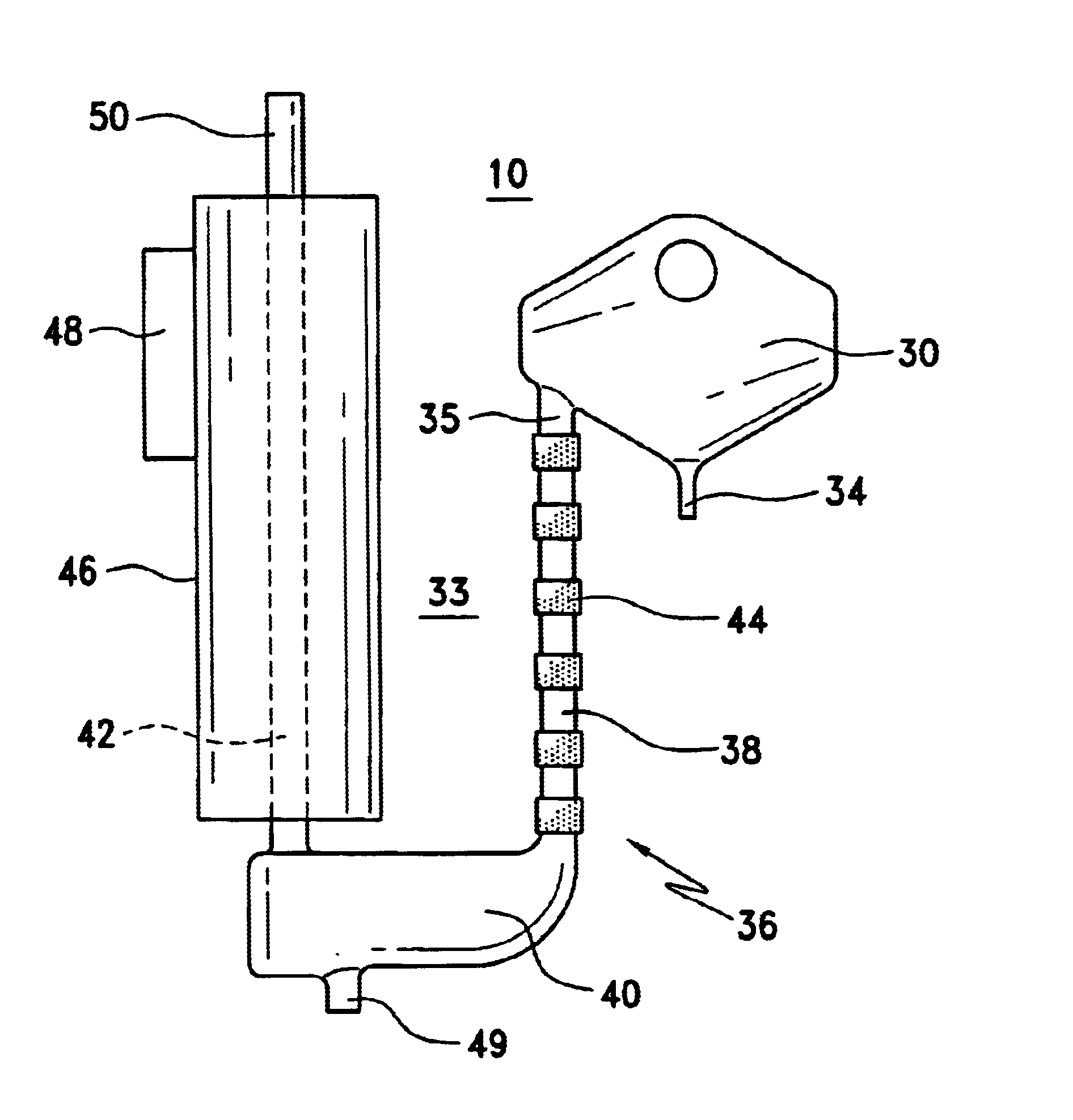
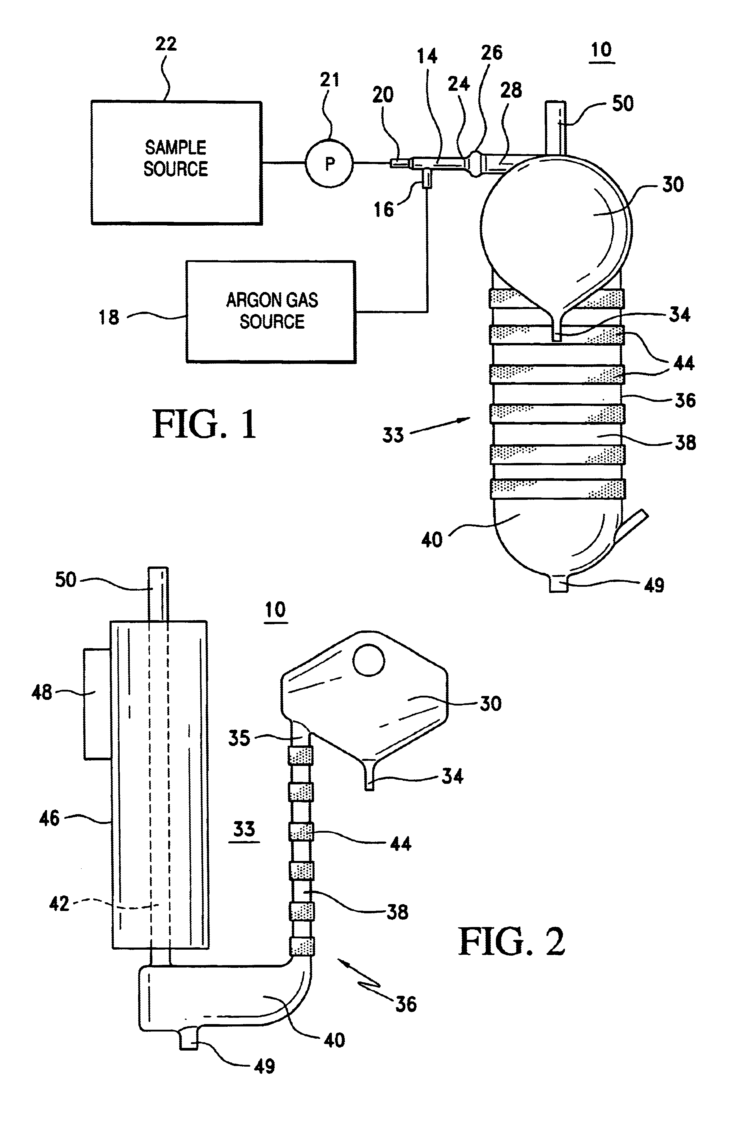
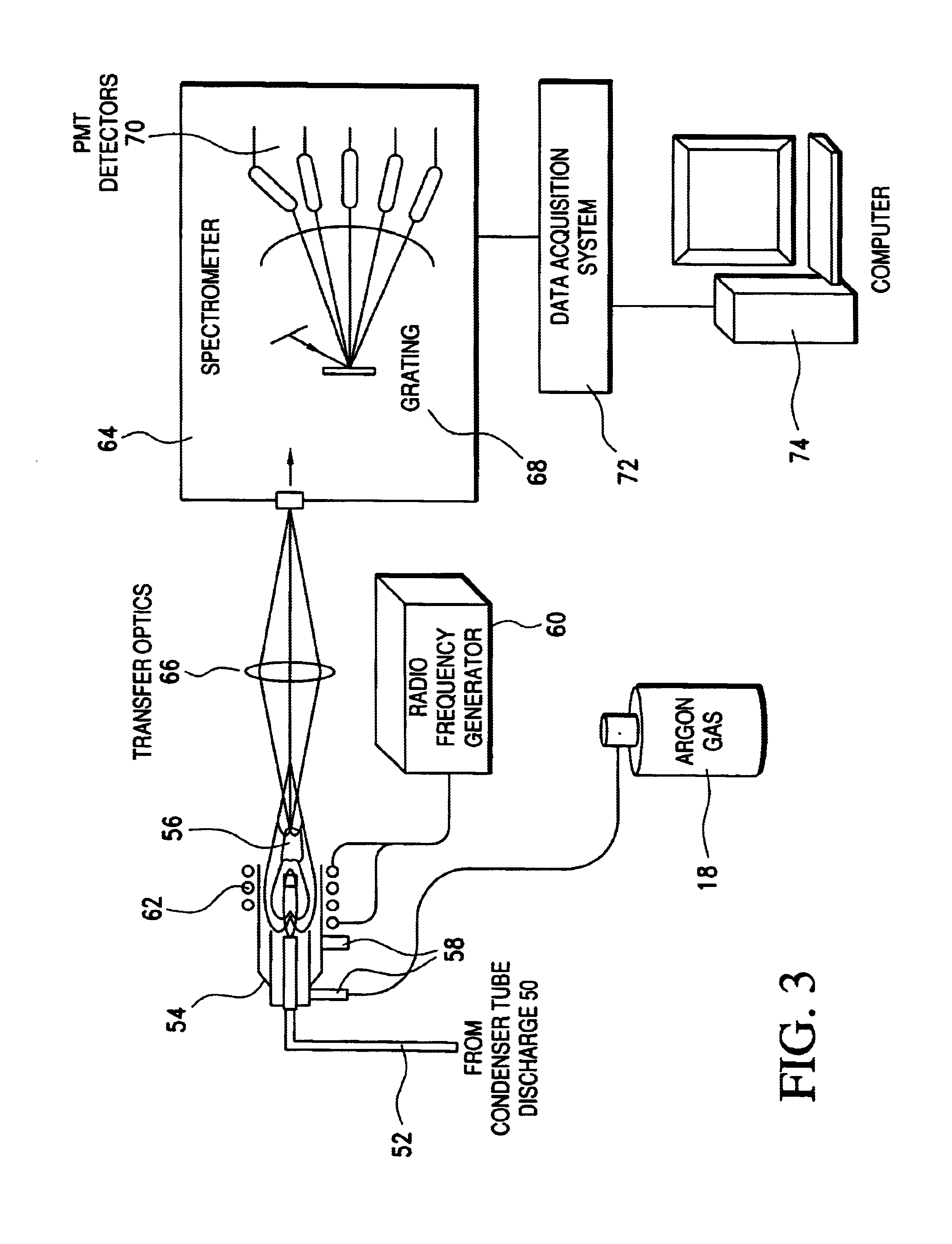
With reference first to FIGS. 1 and 2, a sample generating and injecting system 10 is illustrated that is constructed in accordance with the preferred embodiment for generating and injecting atomized samples into a plasma emission spectrometer. The system 10 combined with a spectrometer system 12 illustrated in FIG. 3 form the overall spectrometer based sample analysis system. The sample generating and injecting system 10 is capable of producing an aerosol comprised of small, evenly sized liquid particles in a carrier gas. Liquid samples may include, for ex...


PUM

PropertyMeasurementUnit
outer diameteraaaaaaaaaa
inner thicknessaaaaaaaaaa
diametersaaaaaaaaaa

Abstract

A system atomizes liquids into a gaseous medium for formation and injection of a sample into an analytical apparatus, such as a plasma spectrometer. The system employs a high efficiency nebulizer that generates a fine aerosol through use of a nozzle having improved surface wetness characteristics, preferably in combination with a deflecting surface. A desolvator is employed to remove excess solvent from the atomized sample prior to injection into the spectrometer to avoid temperature reduction or extinguishment of the plasma by the sample.

Description

BACKGROUND OF THE INVENTION1. Field of the InventionThe present invention relates in general to a system for generating atomized samples and injecting the atomized samples into analytical equipment, such as a plasma emission spectrometer, for example.2. Description of the Background ArtPlasma emission spectrometers are highly sensitive devices that are employed to analyze samples for the presence of various elements or impurities therein. For example, drinking water is often analyzed for impurities by using an emission spectrometer. This is an important application due to increasingly strict impurity limits set for drinking water by the EPA. In particular, drinking water may contain trace levels of certain poisonous elements, such as lead and arsenic, but the allowable limits for these impurities are understandably very low. As a result, highly sensitive devices must be used to detect the levels of these impurities.A plasma emission spectrometer operates by subjecting a sample to a ...

Claims


Application Information

Patent Timeline
Patent Type & Authority Patents(United States)
IPC IPC(8): H01J49/04H01J49/02
CPCH01J49/04
Inventor RUTZKE, MICHAEL A.SWEAT, STEVEN D.
Owner CORNELL RES FOUNDATION INC
Why Eureka
Try Eureka