Highly productive method of producing plasma display panel

a plasma display and high-productivity technology, which is applied in the manufacture of electrode systems, electric discharge tubes/lamps, discharge tubes luminescnet screens, etc., can solve the problems of reducing production costs and considerably higher production costs of pdps than crts, and achieve excellent light-emitting intensity and chromaticity, suppress phosphor deterioration, and suppress phosphor deterioration

Inactive Publication Date: 2005-03-01
PANASONIC CORP
View PDF24 Cites 22 Cited by
  • Summary
  • Abstract
  • Description
  • Claims
  • Application Information

AI Technical Summary

Benefits of technology

In contrast, according to the first method described above, the substrates disposed to face each other are heated while a dry gas containing oxygen is circulated in the internal space. This prevents the phosphors and protecting layer from being exposed to high-temperature, high-density gases such as released gases and burning gases, suppressing deterioration of the phosphors by heat and quality change of the protecting layer.
Also, according to the second method described above, the substrates are heated while they are separated. With this arrangement, even if gases (water or the like) adsorbed on the surfaces of the substrates are released with heat, the released gases are not confined in the internal space. The heated su

Problems solved by technology

A problem of the PDP manufactured as above is how to improve the light-emitting efficiency and the color purity.
However, the producti

Method used


Image

  • Highly productive method of producing plasma display panel
  • Highly productive method of producing plasma display panel
  • Highly productive method of producing plasma display panel

Examples


embodiment 1

Variations of Embodiment 1

(1) In the above embodiment, dry air is circulated in the internal space. However, a dry gas containing oxygen (an inert gas such as nitrogen) may be supplied to obtain the same effect.(2) In the production method described in the above embodiment, a constant amount of dry air is supplied to the internal space. However, the flow rate of the supplied air may be changed as necessary. Also, evacuation of the internal space and supply of dry air may be alternated. This enables oxygen to be supplied to the internal space and enables water vapor or the like that are generated in the internal space to be exhausted from there. This method also provides the above effect to some extent.(3) In the production method described in the above embodiment, a typical glass frit is used as the sealing material. However, a crystalline glass may be used instead. A typical crystalline glass is a PbO—ZnO—B2O3 base frit glass.

In the case where a normal frit glass is used as the sea...

examples

TABLE 1FRITSOFTENINGCRYSTALLIZATIONREQUIREDEXAMPLETEMPERATURE(°C.)POINTTEMP.TIMENo.PROFILET1T2T3T4TYPE(°C.)(°C.)(h)1FIG. 8——520350NORMAL450—62FIG. 8——520350NORMAL400—63FIG. 8——520350NORMAL380—64FIG. 8——520450NORMAL450—65FIG. 8——520200NORMAL450—6.56FIG. 9——520350NORMAL450—7.57 FIG. 10—450520350CRYSTALLINE3804506.5GLASS8 FIG. 11380—520350NORMAL450—9.59 FIG. 12520350520350NORMAL380—15

examples no.1-8

Examples No. 1-8 shown in Table 1 are PDPs manufactured by the method shown in Embodiment 1. In manufacturing these example PDPs, the frit preliminary baking process, phosphor baking process, and panel bonding / exhausting process are performed based on the temperature profiles shown in FIGS. 9-12, as shown in Table 1.

The example No. 9 is a PDP manufactured by a comparative method. In manufacturing this example PDP, the frit preliminary baking process, phosphor baking process, bonding process, and panel bonding / exhausting process are performed based on the temperature profile shown in FIG. 13.

The signs T1-T4 appearing in Table 1 and FIGS. 9-13 represent the following temperatures.T1: frit preliminary baking temperatureT2: frit crystalline temperatureT3: phosphor baking and panel bonding temperature (peak temperature)T4: exhausting temperature

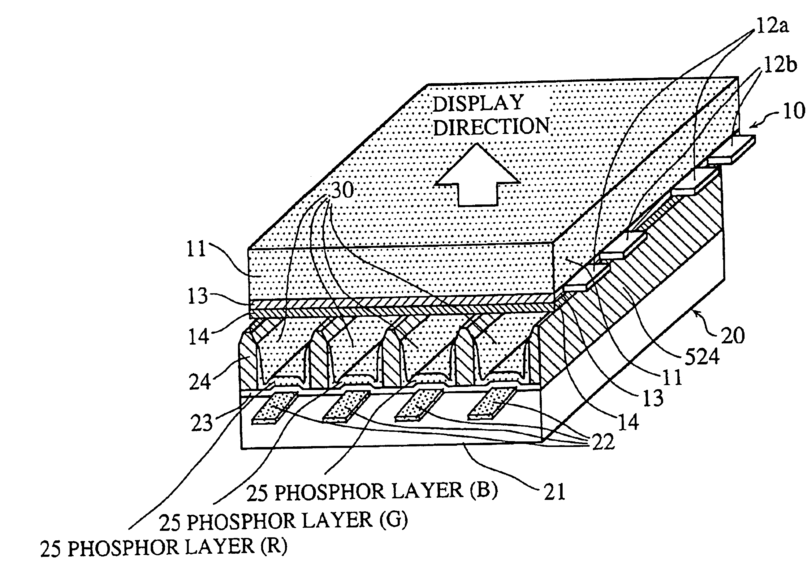
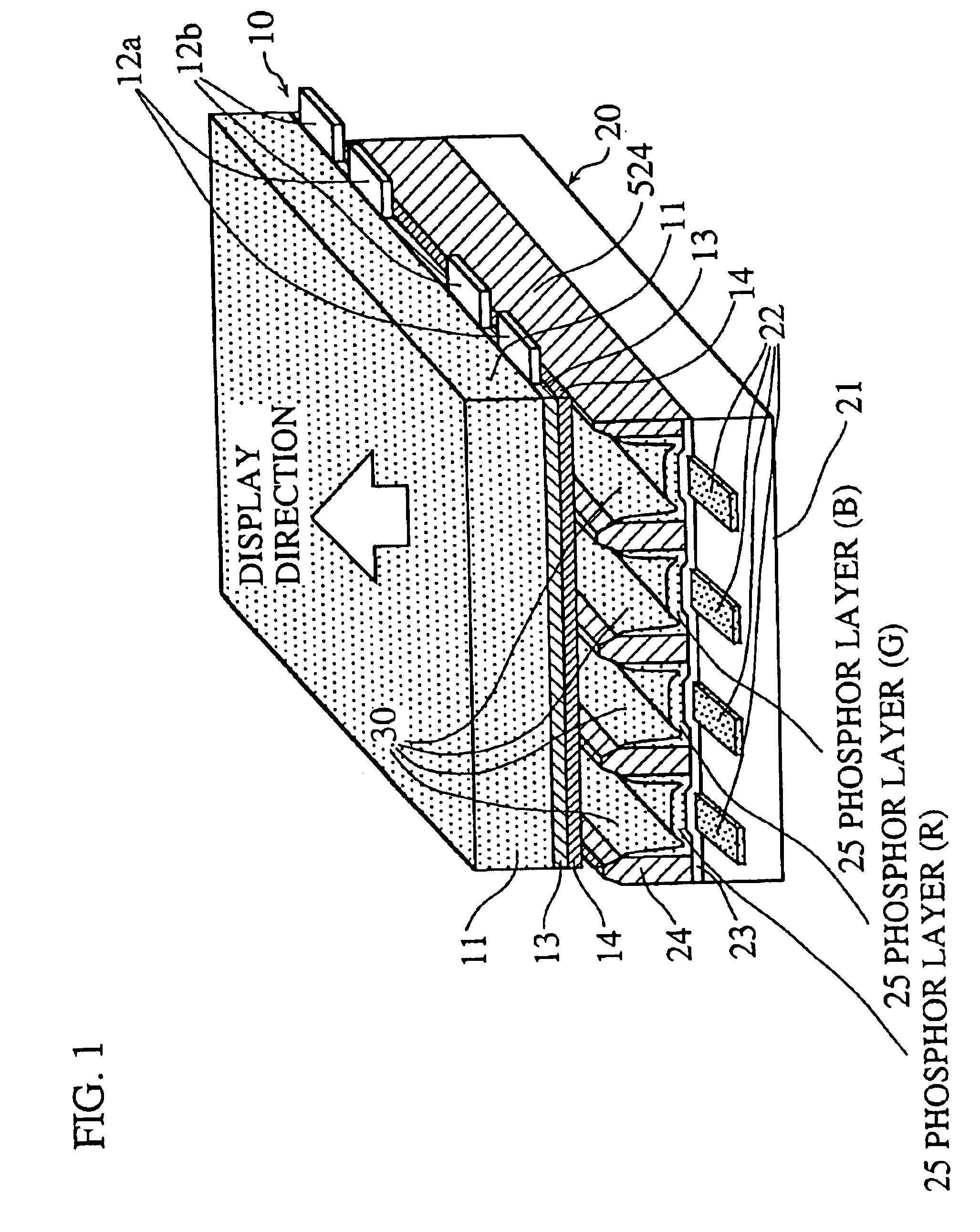
It should be noted here that when each of Example PDPs No. 1-9 is manufactured, partitions 15a are formed when the sealing glass layer 15 is form...


PUM


Abstract

A method for producing a plasma display panel that has a front substrate and a back substrate disposed to face each other. A pre-baking phosphor layer containing a phosphor and an organic binder is formed on at least one of surfaces of the front substrate and the back substrate that are to face each other. A sealing material that softens with heat is applied to the peripheral region of at least one of the surfaces of the front and back substrates that are to face each other. The front and back substrates are disposed to face each other in a stack. The front and back substrates are heated to burn out the organic binder while supplying a dry gas containing oxygen to an internal space that is formed between the front and back substrates.

Description

BACKGROUND OF THE INVENTION(1) Field of the InventionThe present invention relates to a method of producing a plasma display panel used as a display of a color television receiver or the like.(2) Description of Related ArtPlasma display panels (hereinafter referred to as PDPs) have recently received attention as display apparatuses suitable for computers and televisions, being thin and light with large screens. The demand for high-definition PDPs are also increasing.FIG. 20 is a schematic sectional view of a typical AC type PDP.As shown in FIG. 20, a display electrode 102 is formed on a front glass substrate 101, and the display electrode 102 is covered with a dielectric glass layer 103 and a protection layer 104 that is made of magnesium oxide (MgO).Address electrodes 106 and barrier ribs 107 are formed on a back glass substrate 105. Phosphor layers 110-112 of colors red, green, and blue are formed in spaces between barrier ribs 107.The front glass substrate 101 and the back glass ...

Claims


Application Information

Patent Timeline
IPC IPC(8): H01J17/49H01J9/02H01J9/26H01J9/227H01J11/12H01J11/24H01J11/26H01J11/46H01J11/48
CPCH01J9/261H01J11/12H01J9/39H01J9/385H01J9/24H01J11/42
Inventor MIYASHITA, KANAKOKADO, HIROYUKI
Owner PANASONIC CORP
Why Eureka
Try Eureka