Flexible and mobile high transition rate of temperature test devices

Inactive Publication Date: 2005-03-08
NAT CHUNG SHAN INST SCI & TECH
View PDF19 Cites 27 Cited by
  • Summary
  • Abstract
  • Description
  • Claims
  • Application Information

AI Technical Summary

Benefits of technology

The object of this invention is to provide a high temperature change rate test device that can quickly be set up with any kind of shaker. Structurally, the device is provided with a cabinet body with an interior for placing test samples. The cabinet body includes the elements of fans, electric heaters, liquid nitrogen pipes and nozzles therein. Cryogenic valves should be put as near the nozzles as possible to get a better control. The cryogenic valves are fixed on the outer wall of the cabinet. Temperature sensors are movably disposed in the test space. The cabinet body and control system are separate, the power cords, control wires, and temperature sensors are interconnected by connectors to enable the cabinet body to be moved. Liquid nitrogen pipes connecting the cabinet body are also flexible interconnecting hoses. To achieve temperature stability when temperat

Problems solved by technology

The mobility and form of test assembly has little flexibility.
The precision of temperature control of liquid nitrogen used is not satisfactory.
In addition if achieving a high temperature change rate for

Method used


Image

  • Flexible and mobile high transition rate of temperature test devices
  • Flexible and mobile high transition rate of temperature test devices
  • Flexible and mobile high transition rate of temperature test devices

Examples


Embodiment Construction

The following descriptions are of exemplary embodiments only, and are not intended to limit the scope, applicability or configuration of the invention in any way. Rather, the following description provides a convenient illustration for implementing exemplary embodiments of the invention. Various changes to the described embodiments may be made in the function and arrangement of the elements described without departing from the scope of the invention as set forth in the appended claims.

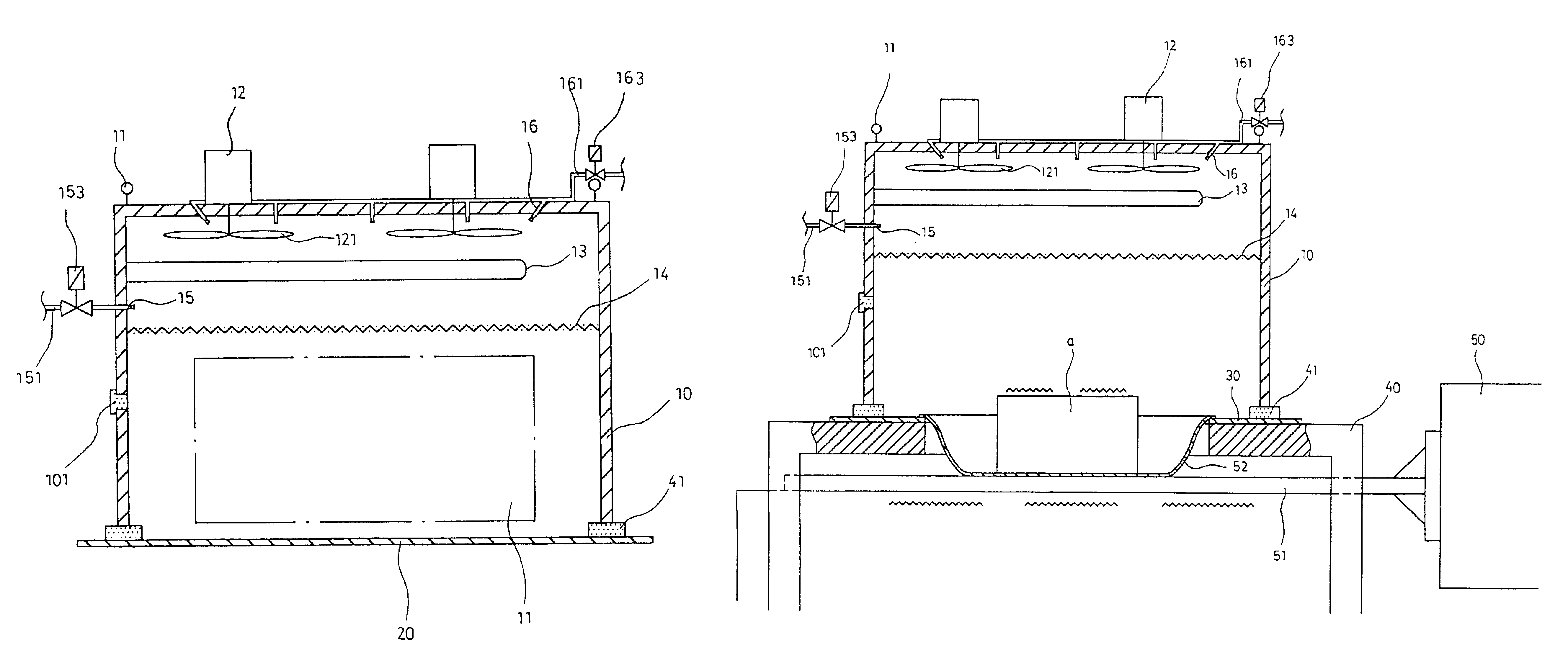
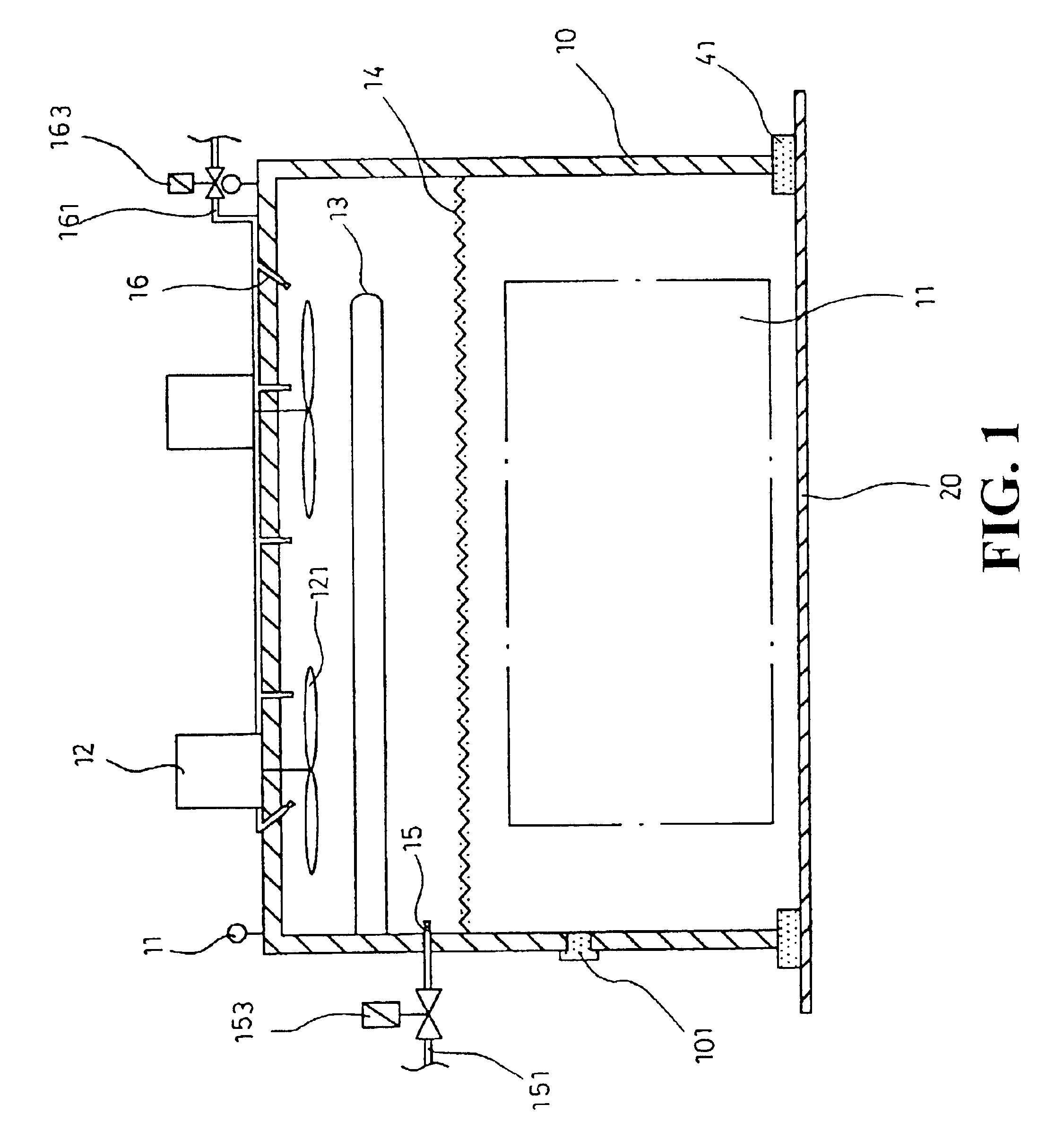
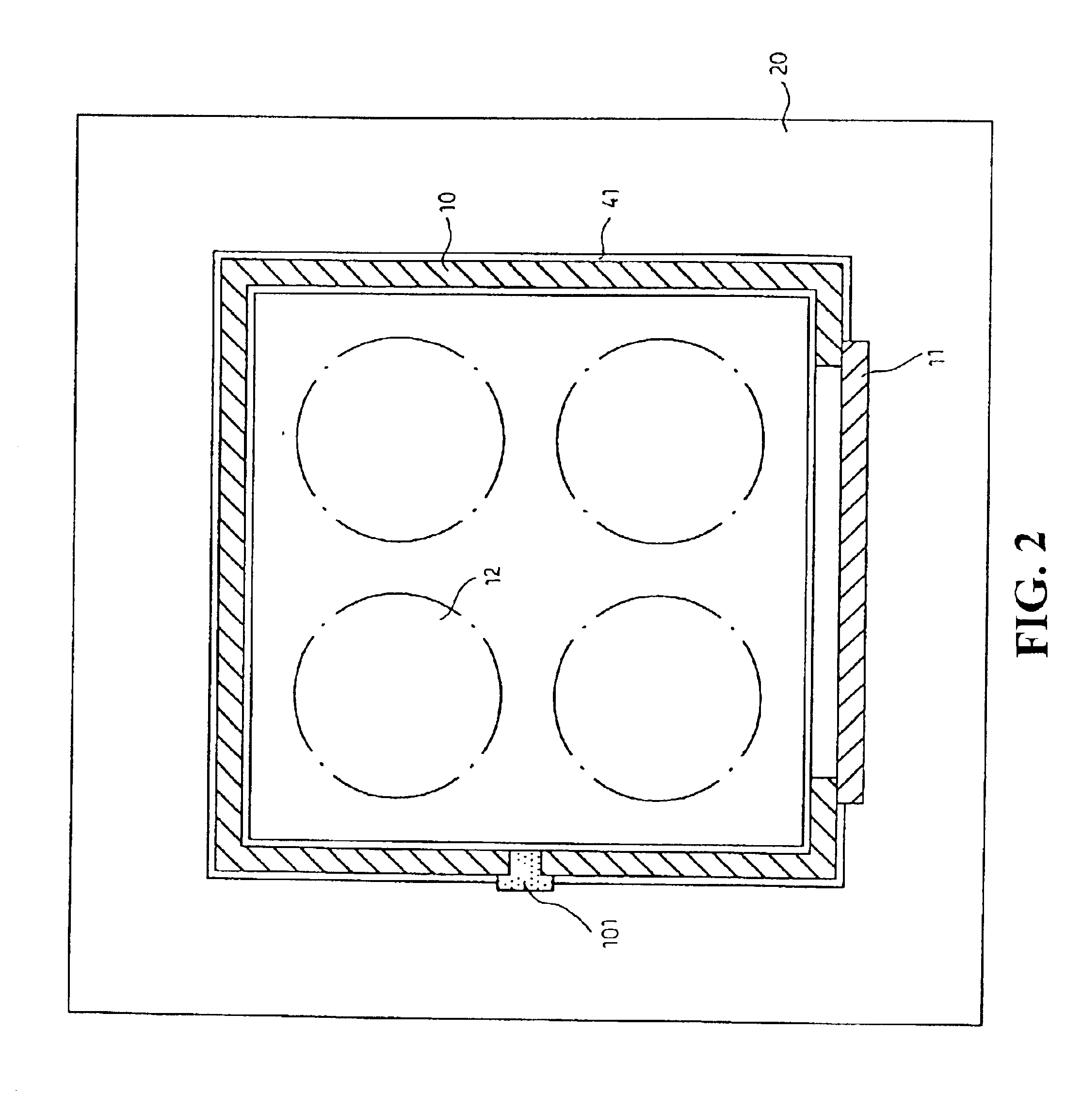
Referring to FIGS. 1 and 2, this invention structurally is provided with a cabinet body 10 with five sides made from heat insulating cabinet walls (e.g., inner and outer layers of the cabinet wall are SUS#304 stainless steel; laminate layers are glass fiber) so that test samples (such as electronic hardware) can be placed in its interior for conducting high thermal rate tests. The cabinet body 10 itself is not provided with a bottom wall so as to match a bakelite baseplate 20 not provided with an openi...


PUM


Abstract

A high thermal change rate of test apparatus aims to realize test equipment requirement of highly accelerated life test(HALT) and highly accelerated stress screening(HASS). Structurally, the apparatus is provided with a cabinet body with an interior for placing test specimen. The cabinet body is provided with elements of fans, electric heating tubes and liquid nitrogen nozzles therein. The positions of the cabinet body and the control system are separate. Several groups (normally 2 or 3 groups, depends on the size of cabinet) of liquid nitrogen pipes connecting the cabinet body are flexible stainless steel pipes for enclosing and insulating sleeve tubes. During full-speed temperature cooling, all groups of the pipes simultaneously eject liquid nitrogen. When temperature is constant, only one group of liquid nitrogen pipe with cryogenic valve and nozzles is used and micro-adjusted to achieve good temperature stability. The cabinet body can match different types of shaker combinations to perform temperature/vibration test with high transition rate of temperature, and be used as a single high thermal change rate of temperature cabinet, can have relatively great assembly flexibility in response to test requirement. The entire apparatus has higher mobility and flexibility than conventional temperature/vibration cabinets.

Description

BACKGROUND OF THE INVENTION(a) Field of the InventionThis invention relates to a high thermal change rate test device, and more particularly to the following: (1) In response to test form requirements, mobility is high, there is great of flexibility shakers, and more usage. (2). Liquid nitrogen enters the chamber via multiple pipes. Electric heaters are also divided into two groups for control, and to achieve the effects of a rapid rise and fall of temperature, and constant temperature stability. (3). The dispersion effect of spray ejected from liquid nitrogen nozzles is good, and it has a good temperature reduction efficiency and temperature distributing effect when used in the temperature cabinet. (4). Suitable pressure of liquid nitrogen pipes can be adjusted to satisfy cooling rate requirements, and prevent excessive pressure to cryogenic valves lead to loss of control and cause excessively low temperature.(b) Description of the Prior ArtIn a conventional temperature test appara...

Claims


Application Information

Patent Timeline
IPC IPC(8): F25D3/10G01N17/00G01N3/60
CPCF25D3/10G01N17/002G01N3/60
Inventor WANG, JENG-YAUSONG, RUEY-SHYONG
Owner NAT CHUNG SHAN INST SCI & TECH
Why Eureka
Try Eureka