
Distortion compensation device

a distortion compensation and distortion technology, applied in the direction of gain control, amplifier modification to reduce non-linear distortion, digital transmission, etc., can solve the problems of reducing the communication quality of these channels, affecting the accuracy of distortion compensation, and affecting the performance of transmission power amplifiers, so as to improve the power added efficiency of transmission amplifiers, improve the precision of distortion compensation, and improve the effect of distortion compensation stability

Inactive Publication Date: 2005-03-08
FUJITSU LTD
View PDF6 Cites 34 Cited by
  • Summary
  • Abstract
  • Description
  • Claims
  • Application Information

AI Technical Summary

Benefits of technology

In light of the above, an object of this invention is to automatically determine delay times with high precision, and enable the delay times to be set in delay circuits.
Another object of this invention is to enable satisfactory distortion compensation by using accurate delay times, and moreover to enable improvement of the power added efficiency of the transmission power amplifier and reduction of power consumption.
Still another object of this invention is to improve the power added efficiency and lessen heat generation, and by this means to curtail heat generation remedies and reducing the scale of the device.
By means of the above first through third inventions, the timing of the transmission signal and feedback signal in the distortion compensation device can be coordinated automatically and precisely, so that the precision of distortion compensation can be improved, and moreover stable operation of distortion compensation is possible. Further, the power added efficiency of the transmission power amplifier can be improved, and power consumption can be reduced. Also, by improving the power added efficiency, heat generation can be diminished, and heat generation remedies can be curtailed, as a result of which the device scale can be reduced.

Problems solved by technology

In recent years bandwidth resources have become restricted, and there has been widespread adoption of highly efficient digital transmission in wireless communications.
This leakage power is noise with respect to other channels, and causes degradation of the communication quality of these channels.
However, in order to achieve this an amplifier is required with capacity equal to or greater than that actually required, so that there are problems of disadvantageous cost and device size.
Further, in normal amplifiers the power added efficiency in the linear region is low, as seen in FIG. 28, and is large in the nonlinear region.
Thus in order to obtain the required transmission power, a large power consumption is necessary in the nonlinear region, and yet as described above, distortion increases and the ACLR is degraded.
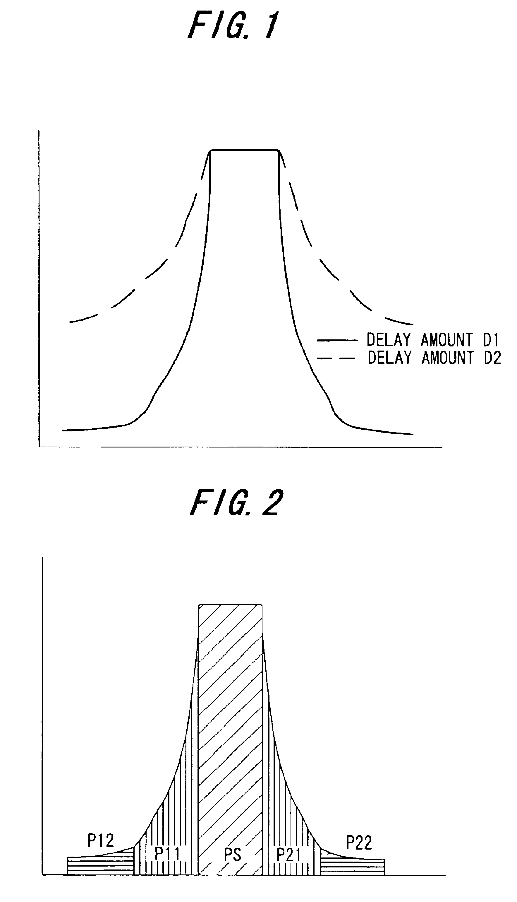
If this delay time D cannot be correctly set, the distortion compensation function will not operate effectively, and the larger the error of the delay time setting, the greater the swelling of the side lobes, and the more pronounced the power leakage into adjacent channels.
Consequently the delay times set in the delay circuits 15m, 15n, 15p for each conventional transmission device are adjusted manually using delay time adjustment switches or similar, and so the task of adjusting delay times is complex, and there is the further problem that precise adjustments cannot be made.

Method used


Image

  • Distortion compensation device
  • Distortion compensation device
  • Distortion compensation device

Examples


first embodiment

(B) First Embodiment

(a) Overall Configuration

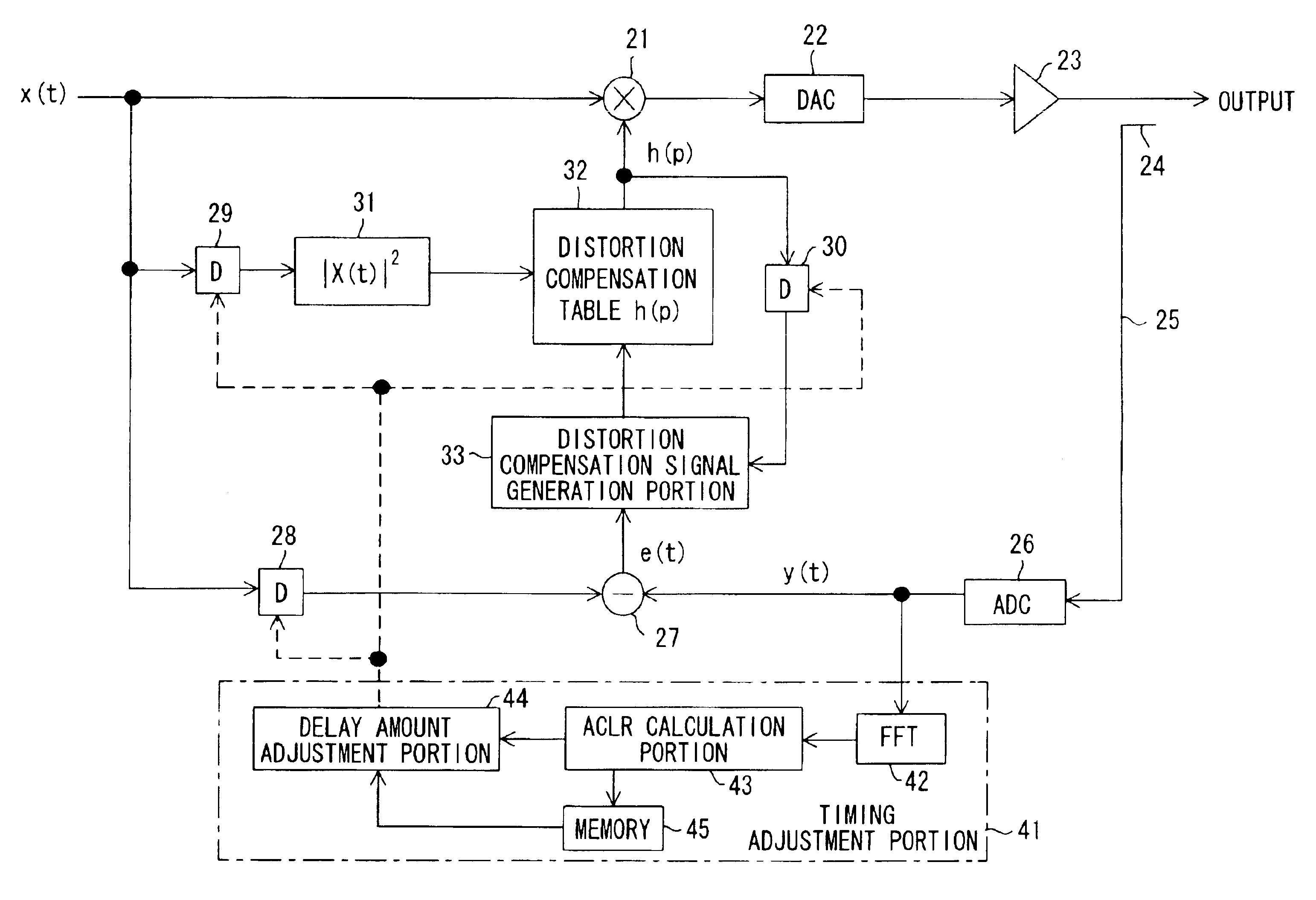
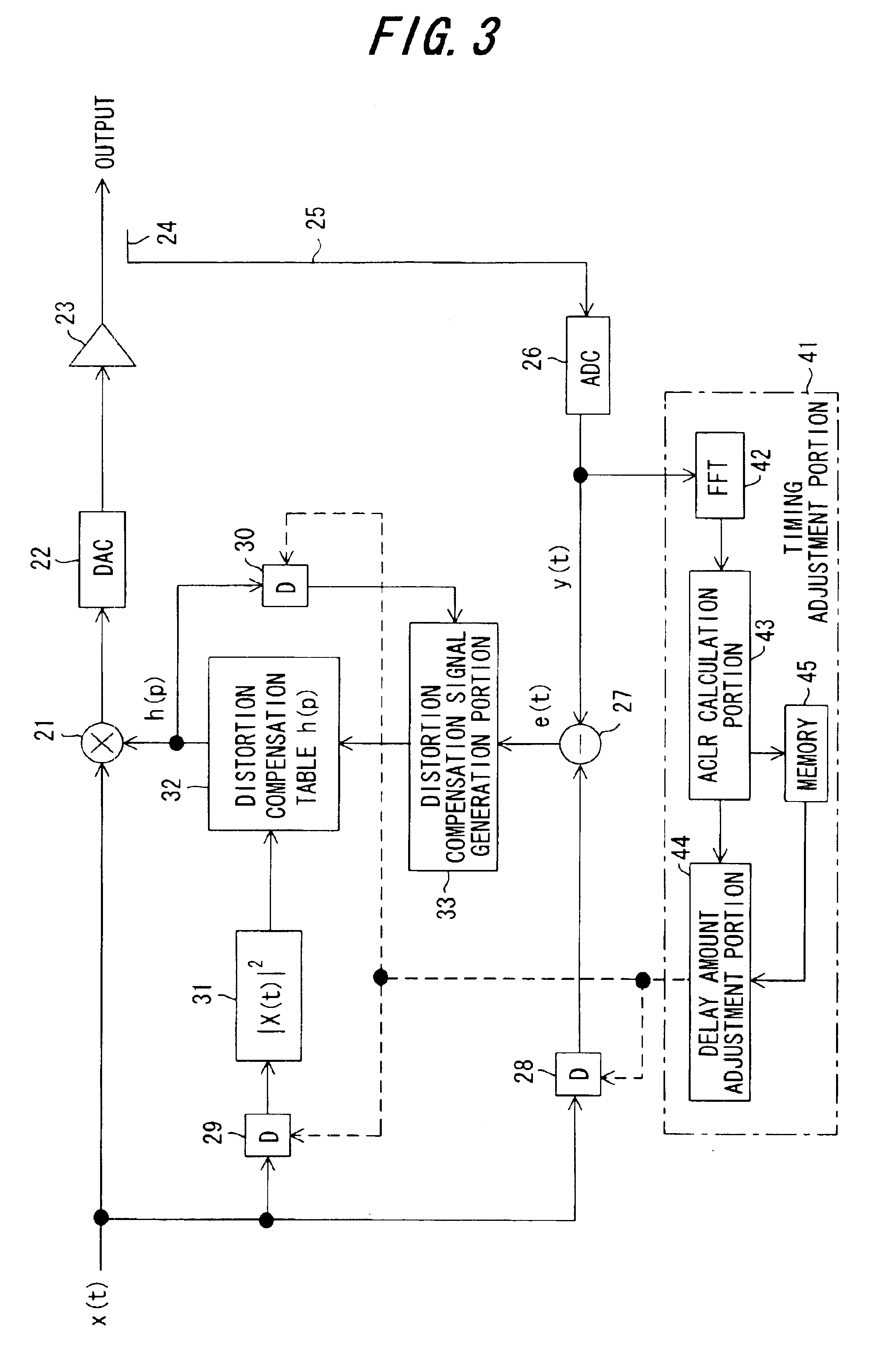
FIG. 3 is a drawing of the configuration of the first embodiment of the invention; 21 is a multiplier which multiplies the digital transmission signal x(t) by the distortion compensation coefficients h(p) to perform predistortion processing, 22 is a DA converter which converts the transmission signal into analog form, 23 is a transmission power amplifier, 24 is a directional coupler which extracts a portion of the transmission signal, 25 is a feedback system which feeds back the output signal from the transmission power amplifier, 26 is an AD converter which converts the analog transmission signal into digital form, 27 is a subtracter which outputs the difference e(t) between the transmission signal x(t) and the feedback signal y(t), 28 to 30 are delay portions which add, to the signal of each portion, the delay time from the time the transmission signal x(t) is input until the feedback signal y(t) is input to the subtracter 26, 31 is a c...

fourth modification example

The overall delay time of the transmission power amplifier 22 and feedback system 25 changes with aging. Hence it is necessary to periodically perform delay time determination processing, and to always set accurate delay times in the delay portions 28 to 30.

FIG. 10 shows the configuration of the fourth modification example in which delay times are determined intermittently; FIG. 11 shows the flow of delay time determination processing of the fourth modification example. Portions which are the same as in the second-modification example of FIG. 7 and FIG. 8 are assigned the same symbols. In FIG. 10, a difference with the second modification example of FIG. 7 is the provision of a timer 61; in the processing flow of FIG. 11, a difference with the processing flow of FIG. 8 is the fact that, when in the initial step 200 the timer 61 specifies the initiation of delay time determination processing, the delay time determination processing of step 101 and below is performed. By means of this...

fifth modification example

The total delay time of the transmission power amplifier 22 and feedback system 25 changes depending on individual differences among devices. Hence the delay time is adjusted at the time of manufacture at the plant to determine the optimum delay time Dopt, which is stored in memory, and during actual use this value is employed to perform distortion compensation control. By this means, there is no need to perform delay time decision adjustment during operation, the timing adjustment portion 41 can be omitted, and there are advantages related to device scale also.

In light of the above, in the fifth modification example a switch 62 is used in place of a directional coupler. The switch 62 inputs the output signal of the transmission power amplifier 22 to the AD converter 26 during delay time determination control, and during operation inputs the output-signal of the transmission power amplifier 22 to an antenna, not shown. As a result, unnecessary waves are not emitted even if delay tim...


PUM


Abstract

In a distortion compensation device which uses distortion compensation coefficients to subject distortion compensation processing to an input signal and supply the result of the distortion compensation processing to a distorting device, calculates the distortion compensation coefficients based on the input signal before distortion compensation and the feedback signal fed back from the output side of the distorting device, and stores the calculated distortion compensation coefficients in association with the input signal, (1) the feedback signal is AD-converted; (2) the AD-converted output is subjected to fast Fourier transform (FFT) processing; (3) the FFT calculation result is used to calculate the value of either the signal-to-noise ratio SNR, or the adjacent channel leakage power ratio ACLR, or the noise level; (4) the delay time occurring in the distorting device and feedback loop is adjusted such that the difference between the above calculated value at the current time and the above calculated value at the immediately preceding time is either zero, or is equal to or less than a threshold value; and, (5) this adjustment processing is repeated to determine the accurate delay time, and based on this delay time the timing of each of the portions of the distortion compensation device is adjusted.

Description

BACKGROUND OF THE INVENTIONThis invention relates to a distortion compensation device, and in particular a distortion compensation device comprising a function which determines the delay time occurring in the feedback loop with the power amplifier from the SNR (signal-to-noise ratio), the ACLR (adjacent channel power ratio), the noise level Pn or similar, and based on the delay time controls the timing within each portion of the distortion compensation device.In recent years bandwidth resources have become restricted, and there has been widespread adoption of highly efficient digital transmission in wireless communications. When employing multivalued phase modulation methods to wireless communication, techniques to linearize the amplification characteristics of the transmitting side and particularly the power amplifier to suppress nonlinear distortion, and to reduce adjacent channel leakage power, are important; further, when using amplifiers with poor linearity to improve power eff...

Claims


Application Information

Patent Timeline
Patent Type & Authority Patents(United States)
IPC IPC(8): H04B1/62H03F1/32H04L27/34H04L27/36H04B1/04
CPCH03F1/3247H04L27/368H04B1/62H03F2201/3233H04B2001/0425H03F1/3241
Inventor ODE, TAKAYOSHIOISHI, YASUYUKIKUBO, TOKURONAGATANI, KAZUOHAMADA, HAJIMEISHIKAWA, HIROYOSHIFUDABA, NOBUKAZU
Owner FUJITSU LTD
Learn More