Cooling device

a cooling device and cooling technology, applied in semiconductor lasers, semiconductor/solid-state device details, lighting and heating apparatus, etc., can solve the problems of low cooling performance of the cooling device, large number of thin plates to make the cooling device thick, and inability to thinne the thickness of the thin layer plate, etc., to achieve high reliability, high power output, and high density of power output

Inactive Publication Date: 2005-03-08
FANUC LTD
View PDF22 Cites 29 Cited by
  • Summary
  • Abstract
  • Description
  • Claims
  • Application Information

AI Technical Summary

Benefits of technology

With this arrangement, the cooling device for constituting a surface illuminating device havi

Problems solved by technology

As a flow rate of coolant necessary for cooling the larger number of LD bars increases, there arises a problem of increasing of a pressure loss of the coolant in the cooling device to fail in securing the required flow rate of coolant, to lower a cooling performance of the cooling device.
Therefore, thickness of the thin layer plate can not be made thinner in view of mechanical strength of the cooling device and the number of thin plates is large to make the cooling device thick.
Further, since it is difficult to form the micro channel by the stamping or chemical etching, the micro channel has to be formed by the laser machining.
As the laser machining of high cost is necessary, a cost of the manufacturing of

Method used


Image

  • Cooling device
  • Cooling device
  • Cooling device

Examples


first embodiment

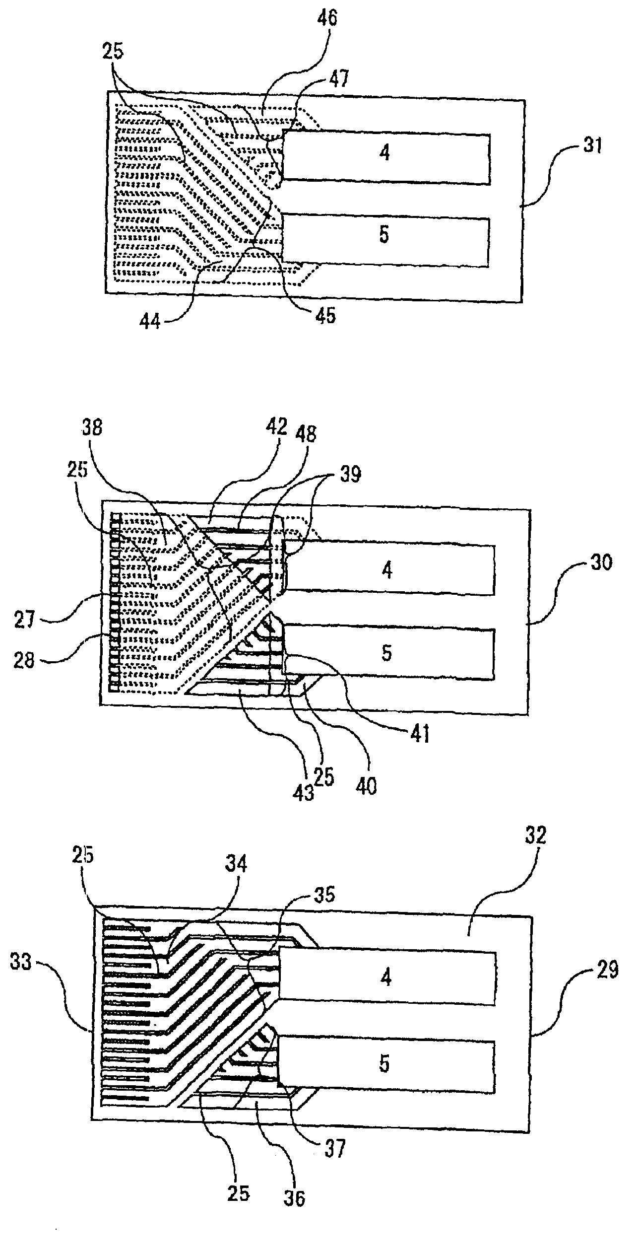
FIGS. 5-7 show a first embodiment of a cooling device according to the present invention. The cooling device of this embodiment comprises a first plate member 29 shown in FIG. 7, a second plate member 30 shown in FIG. 6 and a third plate member 31 shown in FIG. 5. The second plate member 30 is arranged on the first plate member 29 such that a reverse surface of the second plate member 30 and an obverse surface 32 of the first plate member 31 are joined together, and the third plate member 31 is arranged on the second plate member 30 such that a reverse surface of the third plate member 31 and an obverse surface of the second plate member 30 are joined together. Thus, the three plate members 29-31 are laminated to jointly form the cooling device. In this and subsequent embodiment, the terms “obverse” and “reverse” are used on the basis of the state of the plate members as depicted in the figures. Grooves formed on the obverse surface of the plate member are indicated by continuous li...

second embodiment

FIGS. 8-10 show plate members constituting a cooling device according to a second embodiment of the present invention.

The cooling device of this embodiment comprises the first plate member 29 shown in FIG. 10, a second plate member 49 shown in FIG. 9 and the third plate member 31 shown in FIG. 8. The first and third plate members 29 and 31 are identical to the first and third plate members shown in FIGS. 7 and 5 in the first embodiment, respectively. The second plate member 49 of this embodiment has a structure for improving symmetricalness of the flow passage with respect to a longitudinal central plane perpendicular to the surfaces of the plate members in comparison with the second plate member 30 in the first embodiment.

In the second plate member 49, a third grooved paths 39a formed on a reverse surface thereof communicates with a fourth grooved path 41a formed on an obverse surface thereof through the first opened path 42. The fourth grooved path 41a directly communicates with t...

third embodiment

FIGS. 11-13 show plate members constituting a cooling device according to a third embodiment of the present invention. The cooling device of this embodiment comprises a first plate member 50 shown in FIG. 13, a second plate member 51 shown in FIG. 12 and a third plate member 52 shown in FIG. 11. The second plate member 51 is arranged on the first plate member 50 such that a reverse surface of the second plate member 51 in FIG. 12 and an obverse surface 32 of the first plate member 50 in FIG. 13 are joined together, and the third plate member 52 is arranged on the second plate member 51 such that a reverse surface of the third plate member 52 in FIG. 11 and an obverse surface of the second plate member 51 in FIG. 12 are joined together, to be laminated to jointly form the cooling device. An inlet opening 4 and an outlet opening 5 are formed on each of the plate members 50-52 at the same positions.

A first grooved path 35 with one end communicating with the inlet opening 4 and the othe...


PUM


Abstract

A cooling device suitable for cooling a laser diode bar constituting a surface illuminating device as a light source for exciting a laser medium of a solid-state laser oscillator of high power. The cooling device is capable of flowing coolant at sufficient flow rate by reducing the pressure loss in the flow passage of the coolant in the device, to realize a light source device of small thickness with high cooling capability and high reliability. The cooling device comprises a first plate member, one or more second plate member and a third plate member to be joined together to form a laminated body. The second plate member has grooved paths formed on both surfaces thereof and having depths greater than a half of thickness of the plate member, and also opened paths for communicating grooved paths formed on the first plate member and the third plate member. The pressure loss in the flow passage of coolant is reduced by increasing a sectional area of the flow passage by the grooved paths and the opened path of the second plate member without lowering mechanical strength of the device and without increasing a manufacturing cost of the device.

Description

BACKGROUND OF THE INVENTION1. Field of the InventionThe present invention generally relates to a cooling device, and in particular to a cooling device for cooling an object, which emits a large amount of heat such as a laser diode (LD) array, to constitute a light source device therewith.2. Description of Related ArtA laser diode array is used as a light source for exciting a laser medium of a solid-state laser oscillator of high power. Laser oscillation of high efficiency is achieved by exciting the solid-state laser medium by the laser diode array which emits a light beam of acute spectrum instead of a conventional light source such a xenon lamp. A two-dimensional laser diode array (surface illuminating device) formed by stacking one-dimensional laser diode arrays (laser diode bars) having a length of approximately 1 cm and an output power of several tens watt is typically used as the exciting light source of the high power solid-state laser.For obtaining a high-power light from t...

Claims


Application Information

Patent Timeline
IPC IPC(8): H01S5/00H01S5/024H01S5/40F28F3/08H05K7/20H01L23/473
CPCF28F3/086H01S5/024H01S5/405H01S5/4031H01S5/02423
Inventor TAKIGAWA, HIROSHISAKANO, TETSURONISHIKAWA, YUJISATO, MASAONAITO, SHINYAMIYATA, RYUSUKEHAYANO, KOJI
Owner FANUC LTD
Why Eureka
Try Eureka