Method for manufacturing a multi-part valve for internal combustion engines

Inactive Publication Date: 2005-03-22
DAIMLER AG
View PDF9 Cites 13 Cited by
  • Summary
  • Abstract
  • Description
  • Claims
  • Application Information

AI Technical Summary

Benefits of technology

An object of the present invention is to manufacture and connect

Problems solved by technology

For this purpose, correspondingly expensive permanent mold materials are needed, such as niobium or tantalum.
Heretofore, however, it has not yet been possible to avoid residual porosity in the stem, even under optimum temperature control.
Conventional approaches to produce multi-part

Method used


Image

  • Method for manufacturing a multi-part valve for internal combustion engines
  • Method for manufacturing a multi-part valve for internal combustion engines

Examples


Embodiment Construction

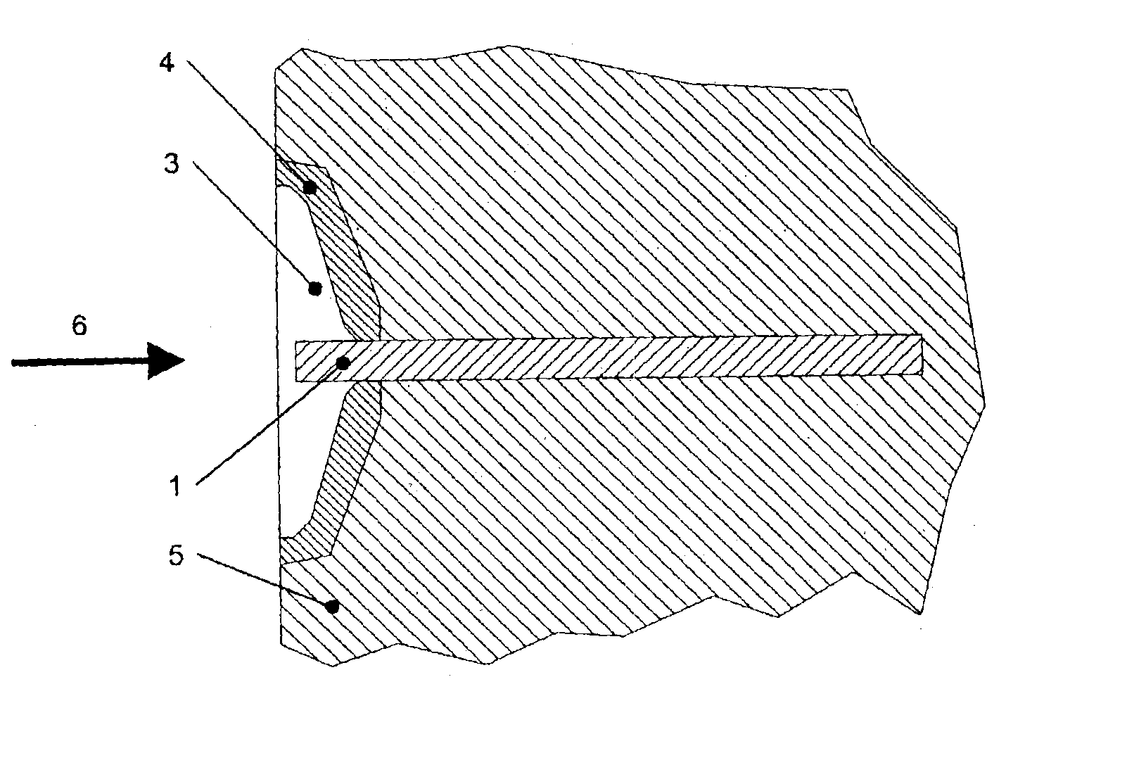
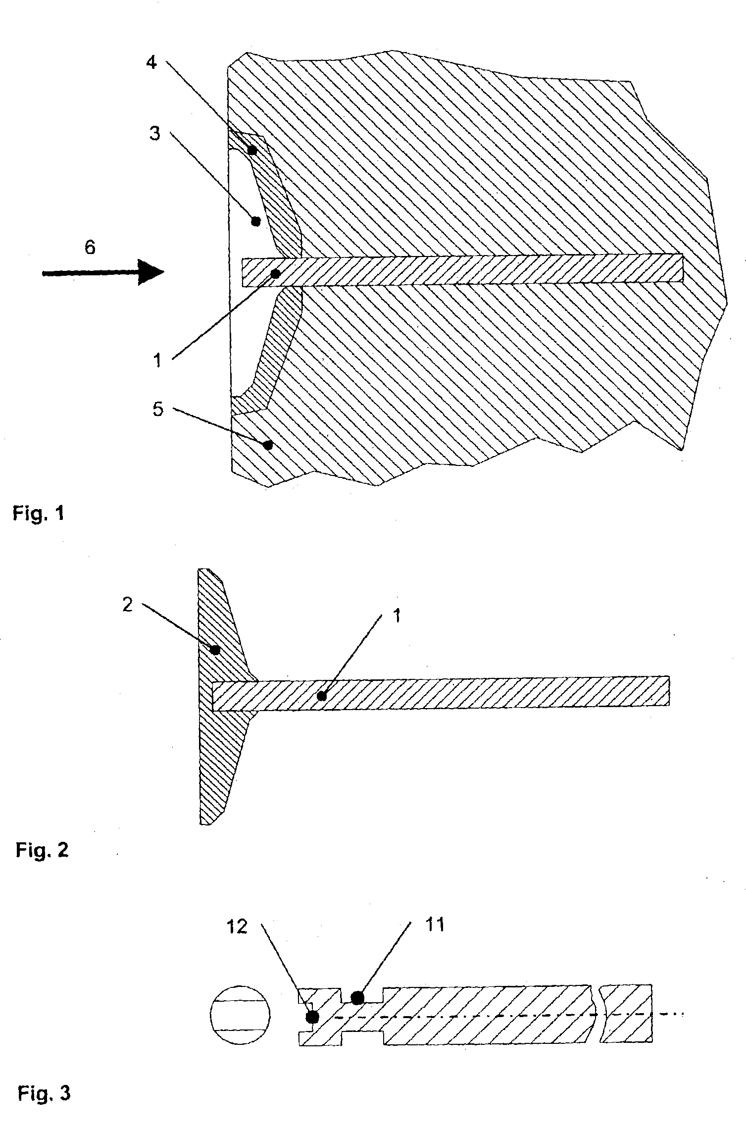
Permanent mold 5 with integrated valve stem 1, which is shown in FIG. 1, is used to manufacture the valves. According to the present invention, it is proposed for permanent mold 5 to be manufactured preferably from a high-temperature resistant steel, and to insert a mold insert 4 into the permanent mold, the mold insert being made of a high-temperature resistant steel or of niobium or tantalum and forming the mold cavity for valve head 2. The permanent mold is provided with a bore whose end is connected to the mold cavity. Valve stem 1 is inserted into this bore. In this context, the length of the bore is selected such that one end of the stem extends from the bore into the mold cavity for valve head 2.

The connection between valve head 2 and valve stem 1 is accomplished by pouring the casting alloy around valve stem 1 (FIG. 2).

The temperature control of permanent mold 5 and of stem 1 located therein is to be implemented such that a controlled solidification in a direction opposite t...


PUM

PropertyMeasurementUnit
Pressureaaaaaaaaaa

Abstract

For making an interconnection between a valve head and stem, the interconnection between these parts is made by pouring a cast alloy around the stem end. A connection and a valve are also provided.

Description

Priority to German Patent Application No. 102 09346.6-24, filed Mar. 2, 2002 and hereby incorporated by reference herein, is claimed.BACKGROUND INFORMATIONThe present invention relates to a manufacturing method for a connection between a valve head and a valve stem of a multi-part valve, to a connection made using the method, and to an automotive engine valve made using the method.Valves used in mass production are mostly based on high-temperature resistant steel, at least in the valve head area. The valve stem is made of less highly alloyed steel and is connected to the valve head by friction welding. In the valve seat area, valve heads are either plasma-coated with a wear-resistant material or hardened. From racing, valves are known that are made of titanium and TiAl. Currently, it is being considered to manufacture and use powder-metallurgically produced or cast solid valves of TiAl.However, cast solid valves can be manufactured using by centrifugal casting or using a kind of a p...

Claims


Application Information

Patent Timeline
IPC IPC(8): B22D17/00B22D17/20B22D19/00F01L3/20F01L3/00F01L3/02F01L3/14B22D19/04B22D21/02B22D21/06F16K1/36
CPCB22D17/007B22D17/2069B22D19/0027F01L3/02F01L3/20Y10T29/49313F01L2101/00F01L2103/00Y10T29/49307F01L2301/00F01L2303/00
Inventor BAUR, HARTMUTBUSSE, PETERWORTBERG, DANIEL BALA
Owner DAIMLER AG
Why Eureka
Try Eureka