Continuous feed coater

a coating machine and feed technology, applied in the direction of electrolysis components, vacuum evaporation coating, coating, etc., can solve the problems of insufficient coating of substrate along the edges, insufficient deposition of material on the substrate, undesired surface, etc., to avoid buckling or wrinkling of the web, reduce the effect of friction

Inactive Publication Date: 2005-03-22
SHIPLEY CO LLC
View PDF24 Cites 24 Cited by
  • Summary
  • Abstract
  • Description
  • Claims
  • Application Information

AI Technical Summary

Benefits of technology

The configuration of the continuous feed coater wherein the deposition plenum walls are provided in large part by the substrates to be coated, provides an advantage over prior art deposition methods and chambers. In prior art deposition methods, a substrate is placed within a deposition chamber and the deposition material is fed into the chamber, resulting in the deposition of the material on the substrate as well as the internal walls of the deposition chamber and other undesired surfaces. Although some portions of the deposition plenum of the present invention (such as side dams) may not be in the form of to-be-coated substrates, a substantial percentage of the deposition plenum is a substrate surface. The efficiency of the process increases as this percentage increases. In some embodiments (such as those having a plenum wall in the form of an observation window) this percentage may be as low as 40%, 50% or 75%. In more efficient embodiments, 90%, 95% and even as high as 99% of the internal surface area of the plenum chamber is in the form of a substrate surface. A simple example to illustrate this would be to consider two 122 cm wide sheets separated by 1 cm (the width of the side dams that seal the plenum chamber). Assuming a uniform width profile along the length of the plenum chamber, this yields a usable substrate percentage of 244 cm / 244 cm+2 cm=99.19%. Of course, the side dams themselves could be strips of substrate material thereby increasing the percentage of usable substrate surface. If the individual sections of substrate contact or touch one another, including purposefully contacting or touching one another, side dams may be unnecessary, although some portions of the substrate along their edges may not be sufficiently coated. Such uncoated or partially coated portions outside of what is herein referred to as the substrate target area, may need to be trimmed in subsequent manufacturing processes.
The deposition techniques of the present invention have an advantage over prior art methods because the deposition material is directed substantially obliquely to and then flows substantially parallel to the substrate (as opposed to other methods wherein the vapor is directed to impinge directly, such as at a perpendicular angle, on the surface and residual material flows away). In this manner, the dwell time is increased, thereby allowing more of the coating constituents to be deposited. Turbulent flow between the substrates and within the deposition plenum, can further increase deposition efficiency and uniformity. While the preferred embodiment is described having a vertical material flow through the deposition plenum, it should be understood that flow through the plenum can be upwards, downwards or sideways depending on the application. As a heated deposition vapor is used in the preferred embodiment, a vertical flow is useful to take advantage of the inherent thermal updraft.
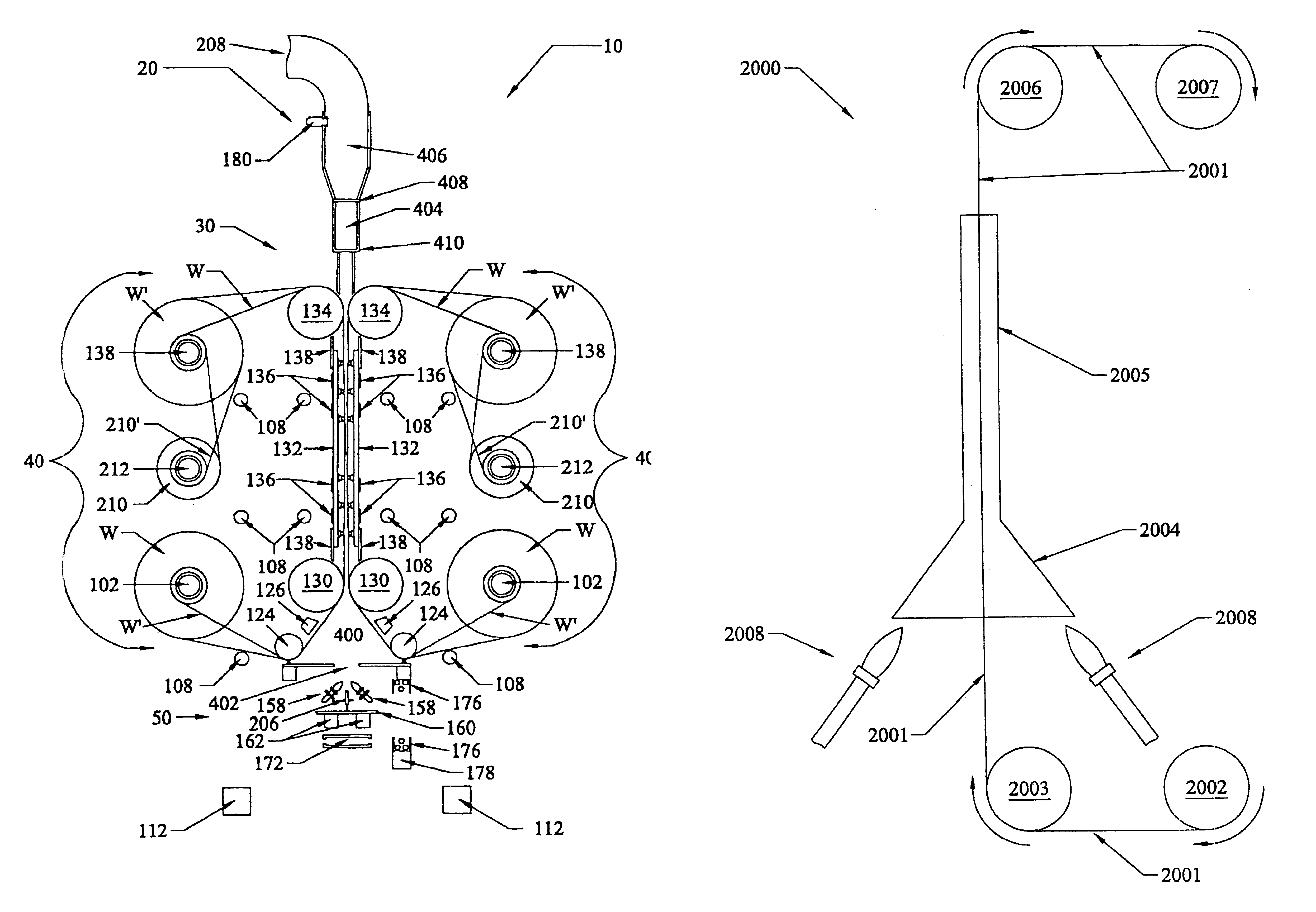
Two different web-handling embodiments are disclosed, the specific embodiment used being dependent on the material being coated. In a first embodiment, within the deposition chamber are a number of horizontally oriented arch bars. These arch bars are made of low-friction material and guide the sheet material so as to form a small bend in the web along a horizontal line. At these locations where the two webs are redirected by arch bars, a venturi effect is created by the change in flow area. This venturi effect creates turbulence in the vapor, breaking down the boundary layer and resulting in a more homogeneous and even coating. The arch bars may alternatively be a type of air bearing wherein air is directed through small holes in the arch bars to support the web in a low friction manner. A second embodiment of the web-handling portion includes a vacuum chuck that holds the two webs flat to avoid buckling or wrinkling of the webs and thereby provide more uniform surfaces and more uniform resulting coatings.
Many coating methods require that the substrates be heated to allow the coating to form on the surface of the substrates. The configuration of the continuous feed coater of the present invention allows for this heating to be done in a number of different ways. Heating bars are provided behind the web substrates in the plenum chamber to provide heating of the substrates while in the plenum chamber. As the substrates enter and exit the plenum chamber, it may be necessary to heat and / or cool the substrates in a staggered or step by step manner. In the roll-to-roll embodiment of the coater, this can be done by heating each of the rollers that route the web to consecutively higher and lower temperatures. When air bearings are used in place of solid rollers, the air can be heated or cooled to control the temperature of the substrate. This heating or cooling is dependent on the materials being used and the final product required. For example, when producing embedded resistors by depositing platinum on copper foil, an initial temperature of the foil is approximately 22° C. (room temperature). For example, in a first stage, the foil temperature is raised, first to 66° C., then to 77° C. and finally to 93° C. in the plenum chamber. Upon leaving the plenum chamber, the foil temperature is reduced to 77° C., then to 66° C. and is finally returned to room temperature. This step-wise increase and decrease in temperature helps to control expansion and contraction of the foil, thereby reducing wrinkling that can degrade the final product. It should be understood that for other applications heating, cooling and possibly both heating and cooling of the substrates may be required at various stages of the deposition process, depending on the materials and products being produced. It is even envisioned that wrinkling or other temperature-induced deformation of the substrates may be desired in some applications.

Problems solved by technology

Of course, while less efficient, one of the larger walls may be replaced with a stationary component such as an observation window.
In prior art deposition methods, a substrate is placed within a deposition chamber and the deposition material is fed into the chamber, resulting in the deposition of the material on the substrate as well as the internal walls of the deposition chamber and other undesired surfaces.
If the individual sections of substrate contact or touch one another, including purposefully contacting or touching one another, side dams may be unnecessary, although some portions of the substrate along their edges may not be sufficiently coated.

Method used


Image

  • Continuous feed coater
  • Continuous feed coater
  • Continuous feed coater

Examples


example

In this example, a platinum / silica coating was formed on two sheets of copper foil to make electrically resistive layers on conductive substrates. The roll-to-roll coater described above was used to form the coatings. A solution containing 40 grams of Pt (II) cychooctadiene, 8 grams of dodecylamine, 27 grams of tetraethyl orthosilicate (TEOS), 750 grams of toluene and 4455 grams of propane was fed to the two CCVD nozzles with a flow rate of approximately 4.85 cc / min per nozzle. Approximately 3.15 amps of current was supplied to the resistively heated atomizers of the CCVD nozzles as was 4.1 liters / min. of tip oxygen. Redirect air was supplied to the central redirect at 43 liters / min. The CCVD nozzles were scanned across the width of the plenum at an average speed of 5 meters / min. The copper foil was fed through the plenum at 21.6 mm / min. The temperature within the plenum was maintained at approximately 90° C., as the flow rate of gas through the plenum had an approximate speed of 14...


PUM

PropertyMeasurementUnit
widthaaaaaaaaaa
widthaaaaaaaaaa
lengthaaaaaaaaaa

Abstract

A continuous feed coater for coating a length of substrate with vaporized or sprayed material, is disclosed. A specific example is a roll-to-roll coater which includes two lower supply rollers for supporting two webs of uncoated material, and two upper take-up rollers for supporting the webs after they are coated. A central web-support forms a plenum that acts as a deposition chimney or chamber by bringing the two webs into close proximity to each other to form two large walls of the plenum. The ends of the webs are sealed using side dams to form the chimney with a rectangular cross section such that the vapor cannot exit from the edges of the material. The vaporized coating constituents to be deposited on the rolled material are directed into the deposition plenum from a coating material supply source located at the bottom of the plenum, and are exhausted through the top of the plenum. By providing a plenum having two large surface area walls formed of the material to be coated, an extremely efficient coating system is provided. The top of the plenum includes an exhaust system with an orifice plate with a plurality of orifices spaced across the width of the deposition plenum. These orifices restrict gas exhaust to provide the gas and vapor residence time for the materials being used.

Description

FIELD OF THE INVENTIONThe present invention is directed to methods and devices for forming thin films and coatings on sequentially fed substrates. In particular, the invention is directed to maximizing the efficiency of the coating process by increasing the effective area of deposition using a roll-to-roll or other sequential feed mechanism to expose a portion of a substrate, web or rolled sheet to the deposition species, and then advancing the substrate(s) to form the desired coating thickness and uniformity.BACKGROUND OF THE INVENTIONSpraying and vapor deposition have been used for many years to produce coatings on substrates by producing a mist or vapor of the deposited material and then exposing a surface of the substrate to the vapor to thereby form the desired coating. In order to conserve the deposited material, and to avoid contaminating the surrounding area, a chamber is used to surround the substrate. In many methods the chamber must be evacuated to provide an oxygen-free ...

Claims


Application Information

Patent Timeline
Patent Type & Authority Patents(United States)
IPC IPC(8): C23C16/453C23C16/44C23C16/54C23C16/00C23C16/455
CPCC23C16/4412C23C16/453C23C16/45563C23C16/545C23C16/45585C23C16/45589C23C16/45591C23C16/45578C23C16/00
Inventor HUNT, ANDREW T.NEILSON, WAYNEOLJACA, MIODRAGREARDON, EDWARD J.HWANG, TZYY-JIUAN JANDANIELSON, JR., WILLIAM D.HUGGINS, JAMES D.BANE, DAVID E.CAMPBELL, IAN H.XUE, YIBIN
Owner SHIPLEY CO LLC
Why Eureka
Try Eureka