
Curable liquid sealant used as vacuum bag in composite manufacturing

a liquid sealant and composite manufacturing technology, applied in the field of composite manufacturing process, can solve the problems of large amount become too expensive, and emitted large amounts of hazardous air pollutants, and achieve the effects of improving chemical resistance, moisture resistance, abrasion resistance, and UV light resistan

Inactive Publication Date: 2005-03-22
COMPOSITES INTELLECTUAL HLDG INC
View PDF15 Cites 57 Cited by
  • Summary
  • Abstract
  • Description
  • Claims
  • Application Information

AI Technical Summary

Benefits of technology

According to yet another aspect of the invention, the polurethane or polyurea formulation can be modified to in order to add enhanced properties, such as improved chemical resistance, moisture resistance, abrasion resistance, ultraviolet light resistance to provide the desired final finish, thereby eliminating the additional step of painting or applying a gel coat.
Yet another embodiment is the method of sealing the flange of the mold. The advantage of the sprayable bag here is that overlaps pleats or seams in the bag do not complicate flange sealing. Resin injection and / or vacuum channels can easily be accommodated by using channel details molded into the flange or by placing a manifold system or resin transfer media on the flange prior to the application of the sprayable bag material.

Problems solved by technology

Closed mold processes can be cost effective when molding relatively small articles, but becomes cost prohibitive when molding large articles, such as boats, because large and intricately matched tooling becomes too expensive.
A significant drawback to open molding techniques is that during the resin deposition stage large amounts of hazardous air pollutants (HAPs) are emitted, which is a matter of increasing concern to the Environmental Protection Agency (EPA).
Therefore, the use of open molds in the fabrication of composite articles is in danger of extinction unless the emission of HAPs can be significantly reduced.
These types of defects can form between the vacuum bag and / or within the reinforced fiber material, causing both structural deficiencies and aesthetic damage to the composite article.
Additionally, wrinkles can form on the surface of the vacuum bag and transfer to the surface of the reinforcing fiber material, causing part defects.
Although slowing down the evacuation process can reduce the occurrence of air pockets, voids, dry spots and / or wrinkles, it also results in reduced production rates, and therefore increased costs.
Any air pockets, voids, dry spots or wrinkles which do form must be manually eliminated via a time-consuming manual smoothing process, which can cause perforation of the vacuum bag or seam separation if not executed properly, and also slows production rates.
Any leaks in the bag will cause air to be introduced into the resin stream.
This problem causes a quality issue commonly called “bubble trails”.
Such defects that are not corrected during the molding process require costly reworking.
Significantly it has been found that vacuum bags manufactured in accordance with the aforementioned prior art can be labor-intensive, and therefore costly.
Finally, reuse of the bag is discouraged, therefore resulting in unwanted solid waste.
Leaks could result in the formation of air pockets, voids or dry spots, and can cause defects in the laminates or HAPS emissions into the atmosphere.
Additionally, as with the aforementioned preformed vacuum bag, the textured film and tape are not reusable, therefore generating unwanted solid waste.
Significantly, it has been found that reusable vacuum bags can be costly and time-consuming to fabricate.
First, costly silicone rubbers capable of withstanding repeated applications must be used.
Second, the fabrication of the reusable vacuum bag requires a labor-intensive process involving elaborate piecing and seaming to protect against air leaks.
Fourth, reusable vacuum bags require regular maintenance such as repairing, cleaning and storing.
Finally, the operational life of the reusable vacuum bag is limited, and the vacuum bag must be eventually discarded and replaced.
This adds to the complexity of the vacuum bag configuration and amplifies the difficulty of placing the bag and ensuring that the bag is completely sealed.
These finishing materials further add to the HAPS emissions during the manufacturing process.

Method used


Image

  • Curable liquid sealant used as vacuum bag in composite manufacturing
  • Curable liquid sealant used as vacuum bag in composite manufacturing
  • Curable liquid sealant used as vacuum bag in composite manufacturing

Examples


Embodiment Construction

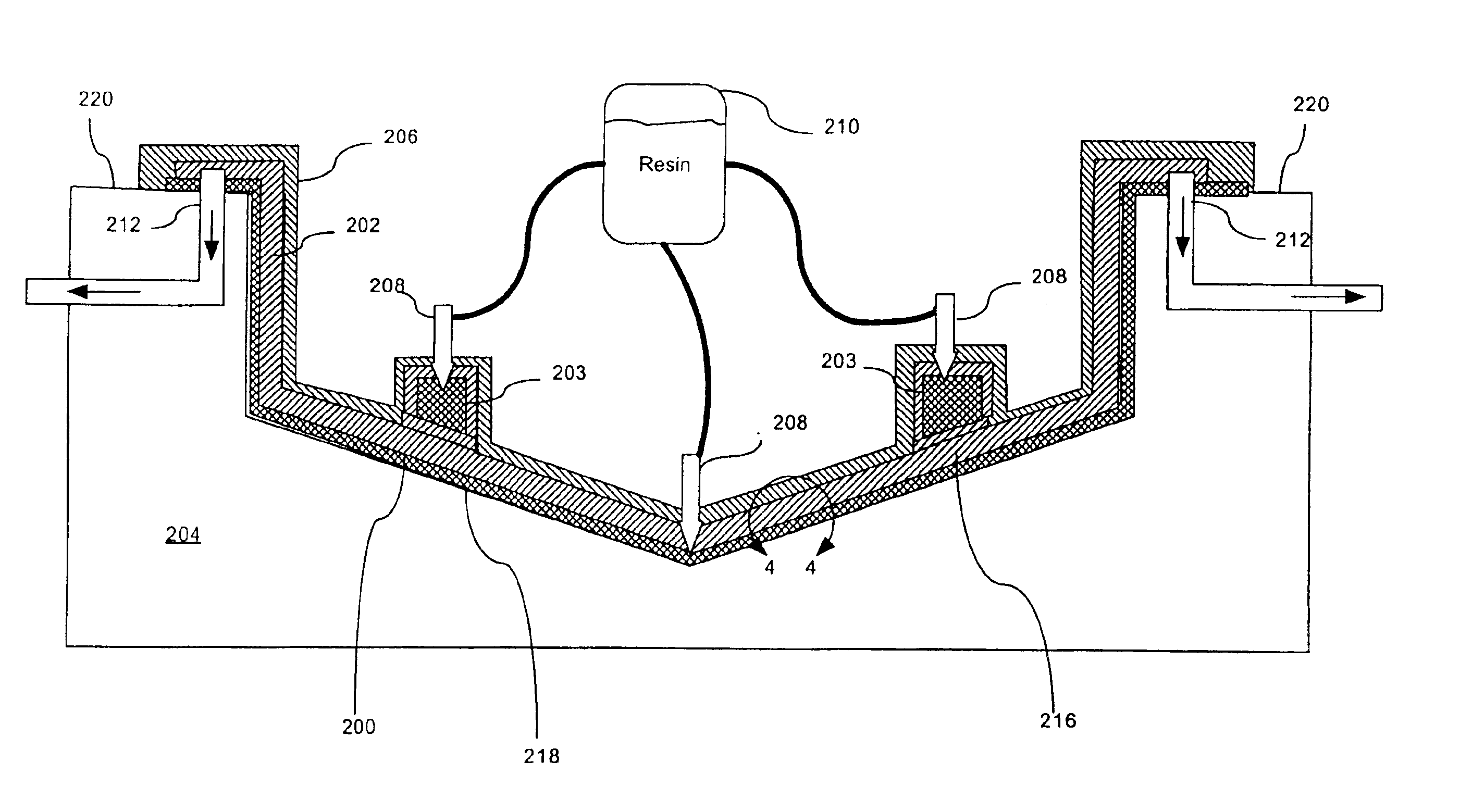
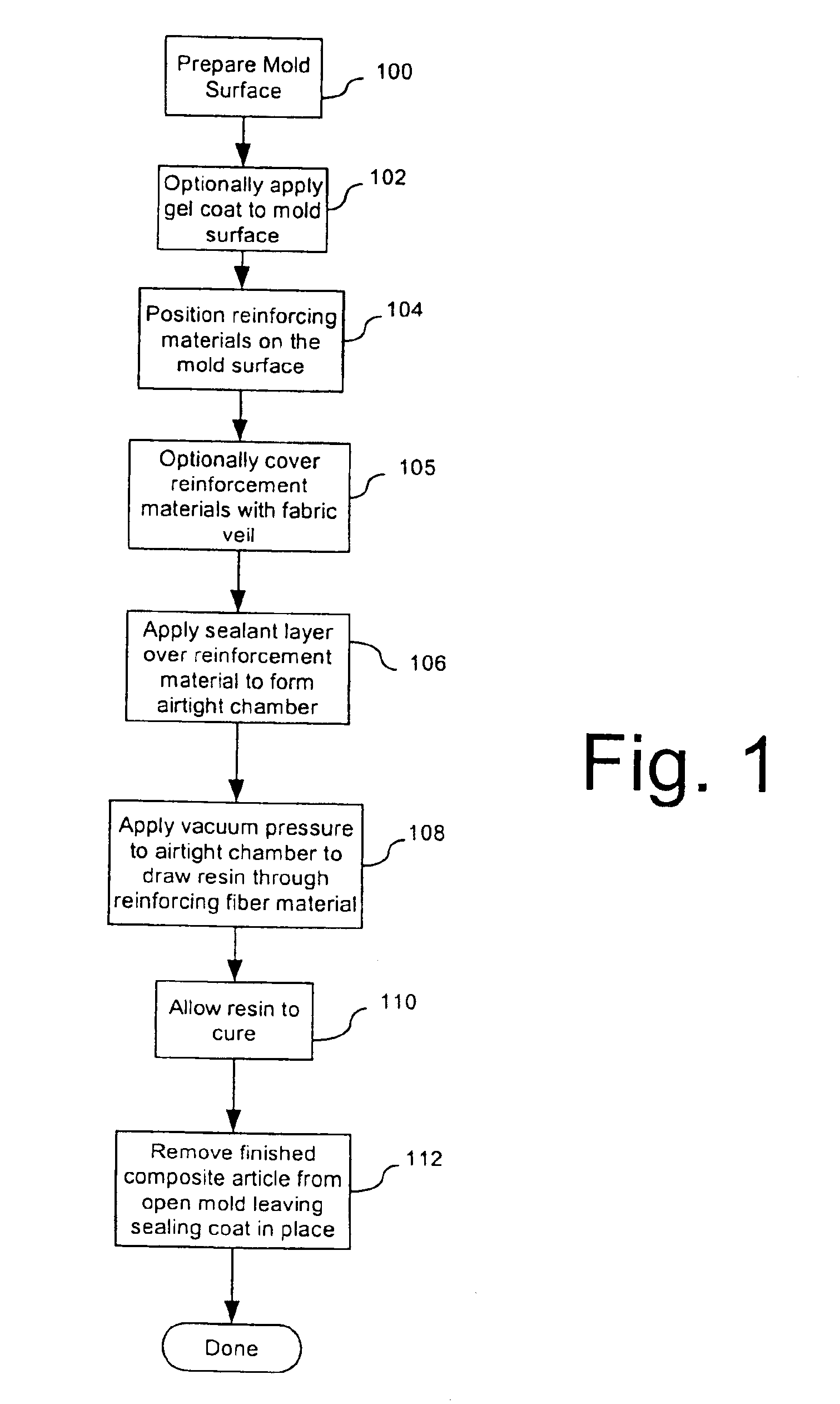
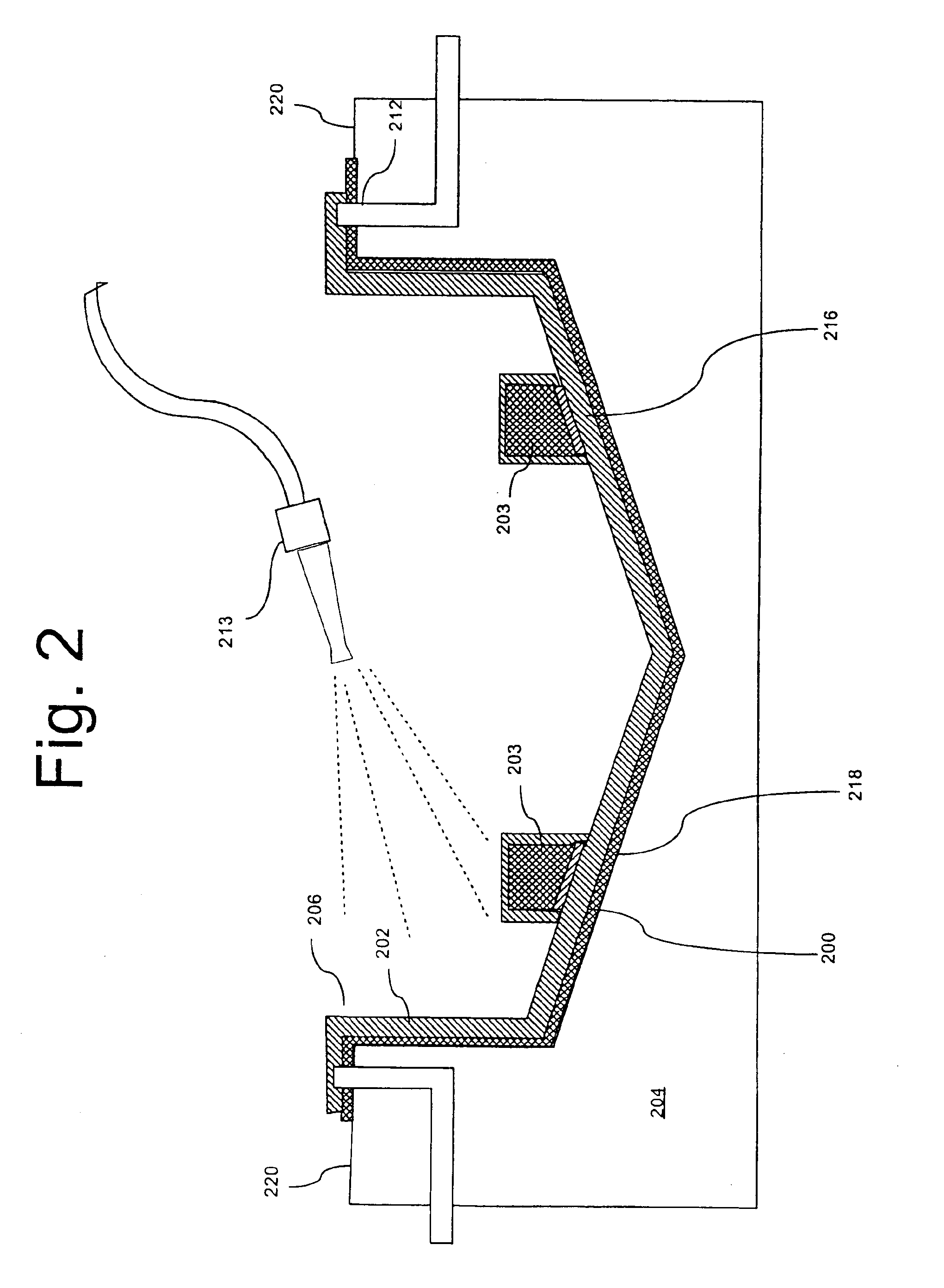
FIG. 1 is a flow chart that shows a process for vacuum assisted resin transfer molding (VARTM) according to the inventive arrangements. The process will be described relative to the cross-sectional view of a mold assembly in FIG. 2. The composite part in FIG. 2 is a boat hull, but it will be readily appreciated by those skilled in the art that the invention is not so limited.

The process preferably begins in step 100 with the preparation of the mold 204. Mold 204 is preferably an open face mold in which the mold surface 218 has a shape that is consistent with a desired composite part to be formed using the process. A flange 220 is preferably provided at the outer periphery of the mold 204. It can be desirable to prepare the mold surface 218 using conventional methods, such as treating the mold surface with wax or the like. However, the invention is not limited in this regard and any other suitable process can be used to prepare the mold 204.

Once the mold surface 218 has been properly...


PUM

PropertyMeasurementUnit
thicknessaaaaaaaaaa
viscosityaaaaaaaaaa
vacuum pressureaaaaaaaaaa

Abstract

The inventive method concerns a process of transferring resin into reinforcing material used in the manufacture of composite articles. A first step in the method involves positioning at least one layer of the reinforcing material on the surface of an open mold. Subsequently, a sealant layer is applied in liquid form over the reinforcing material to create an airtight chamber encapsulating the reinforcing material between the sealant layer and the mold. After the sealant layer is allowed to cure, resin is drawn through the reinforcing material.

Description

BACKGROUND OF THE INVENTION1. Technical FieldThis invention is a process for manufacturing composite articles, and more particularly a process for improving closed vacuum assisted molding techniques used in the fabrication of composite articles.2. Description of the Prior ArtVarious manufacturing methods are used in the fabrication of composite articles. These various manufacturing methods are broadly classified as closed mold and open mold processes. Closed mold processes can be cost effective when molding relatively small articles, but becomes cost prohibitive when molding large articles, such as boats, because large and intricately matched tooling becomes too expensive. Therefore, most large composite articles are currently manufactured using open molds.Open mold processing used in the manufacture of composite articles involves the positioning of reinforced fiber material in a single open mold cavity and spraying or flow coating the reinforcements with liquid curable resin. A var...

Claims


Application Information

Patent Timeline
Patent Type & Authority Patents(United States)
IPC IPC(8): B29C70/04B29C70/44B29C70/34B29C70/54
CPCB29C70/342B29C70/548B29C70/547B29C70/443B29C70/086
Inventor JOHNSON, KEITHLEWIT, SCOTT
Owner COMPOSITES INTELLECTUAL HLDG INC
Features
  • Generate Ideas
  • Intellectual Property
  • Life Sciences
  • Materials
  • Tech Scout
  • Unparalleled Data Quality
  • Higher Quality Content
  • 60% Fewer Hallucinations
Learn More