
Method of preparing metal containing compounds using hydrodynamic cavitation

a technology of hydrodynamic cavitation and metal containing compounds, which is applied in the direction of catalyst activation/preparation, nickel compounds, physical/chemical process catalysts, etc., can solve the problems of high shear and high temperature local heating, decomposition of metal salts to finished metal oxides, etc., and achieve high shear

Inactive Publication Date: 2005-03-22
WORCESTER POLYTECHNIC INSTITUTE +1
View PDF20 Cites 17 Cited by
  • Summary
  • Abstract
  • Description
  • Claims
  • Application Information

AI Technical Summary

Benefits of technology

This method enables the production of high-phase purity, nanostructured materials with precise control over grain sizes, eliminating the need for calcination and resulting in advanced materials like catalysts, piezoelectrics, and ceramics with improved properties and reduced processing hazards.

Problems solved by technology

The synthesis of such materials by hydrodynamic cavitation results in both nanostructured materials as well as high phase purity materials due to the fact that such processing results in high shear and high temperature local heating, applied to the synthesis stream components.
High shear causes the multi—metallics to be well mixed leading to the high phase purities and nanostructured particles, and the high in situ temperatures results in decomposition of metal salts to the finished metal oxides or metals supported on metal oxides.

Method used


Image

  • Method of preparing metal containing compounds using hydrodynamic cavitation
  • Method of preparing metal containing compounds using hydrodynamic cavitation
  • Method of preparing metal containing compounds using hydrodynamic cavitation

Examples


example 1

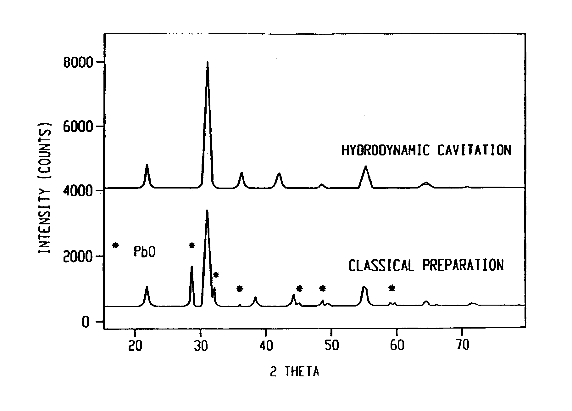
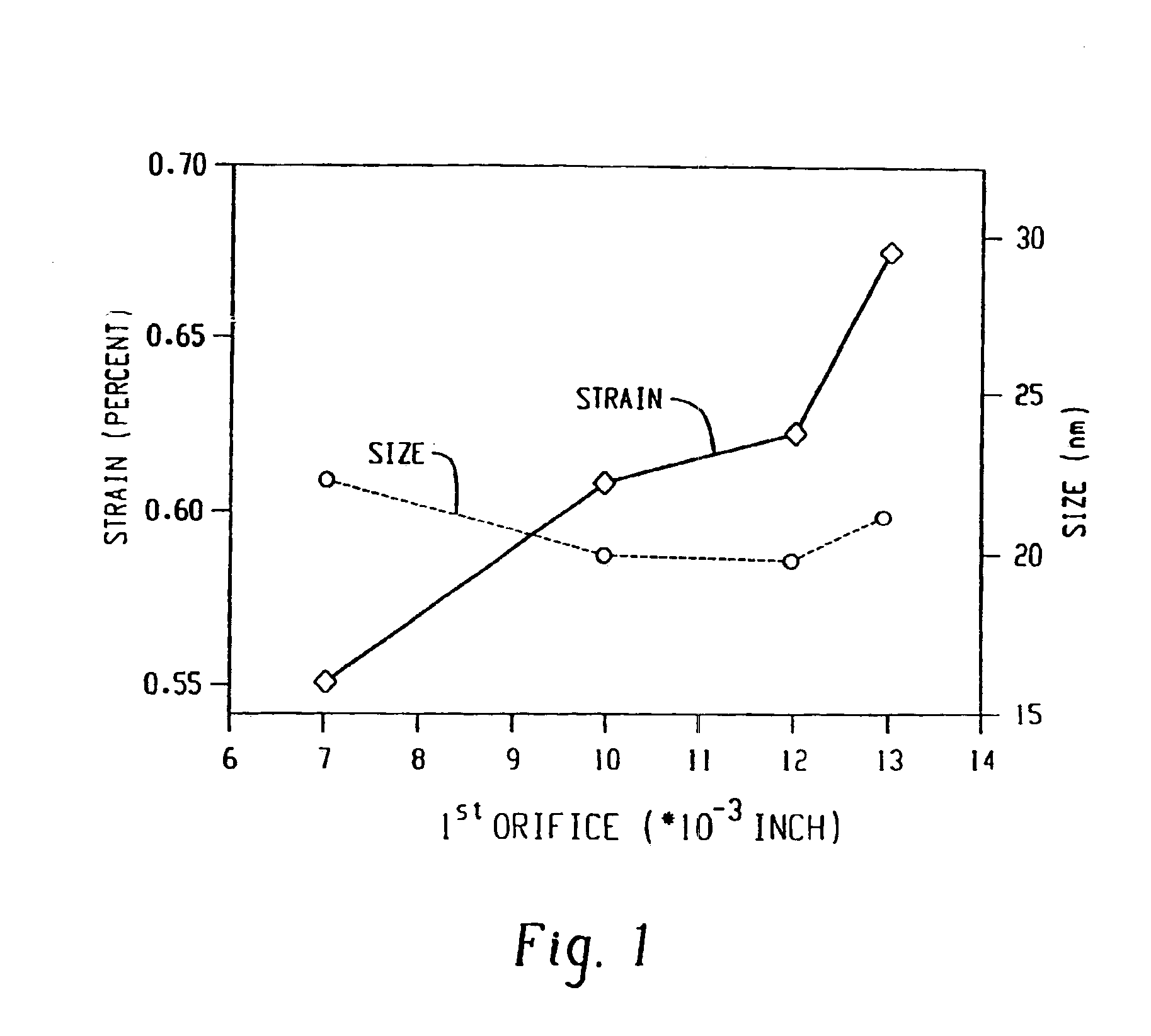
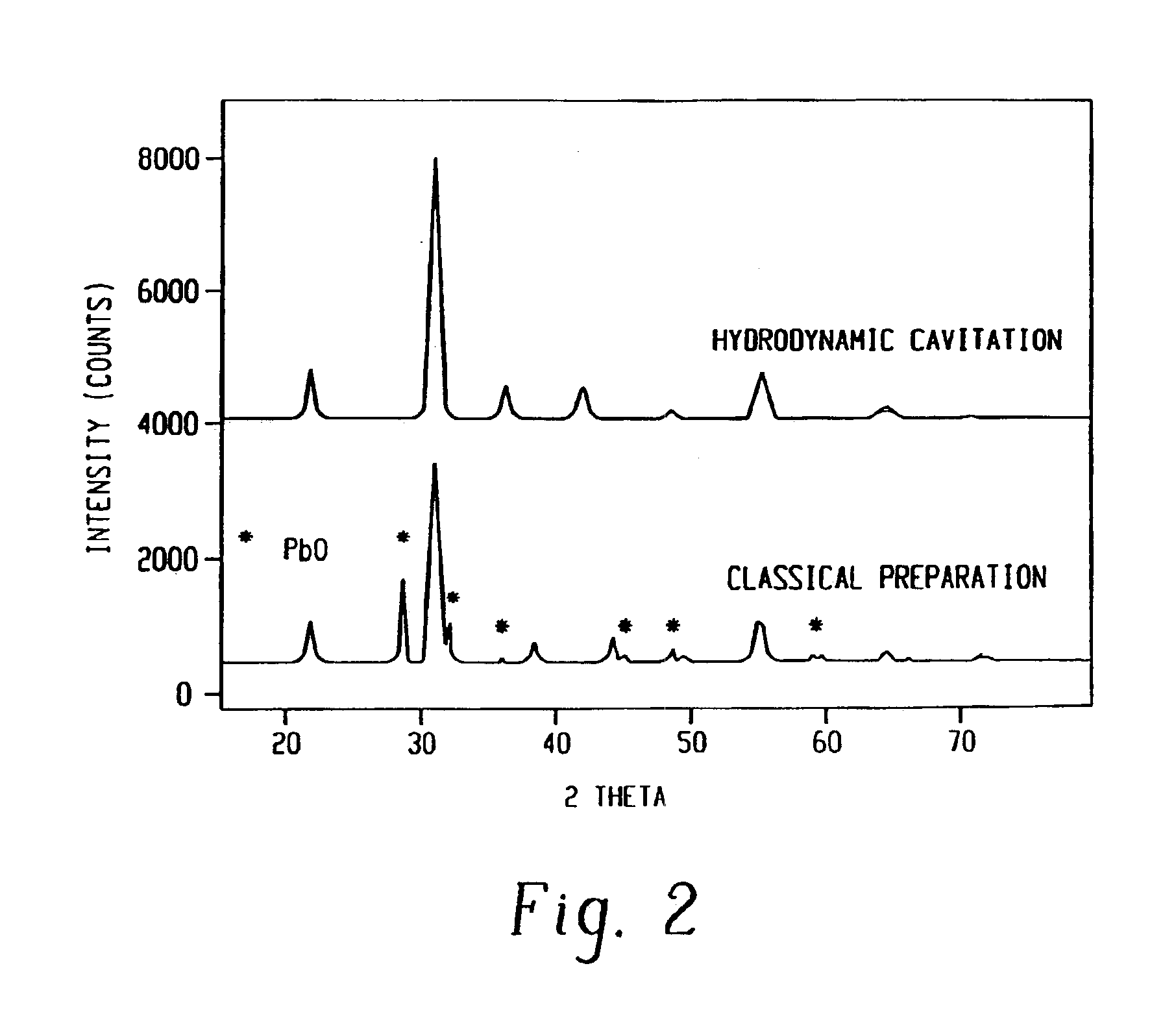
This example illustrates that controlled cavitation enables the synthesis of an important hydrodesulfurization catalyst for use in the environmental clean-up of gasoline in a substantially improved phase purity as compared to conventional preparations. The preparation of cobalt molybdate with a Mo / Co ratio of 2.42 was carried out in the CaviPro™ processor. Different orifice sizes were used for the experiment at a hydrodynamic pressure of 8,500 psi. In each experiment 600 ml of 0.08M of ammonium hydroxide in isopropanol was placed in the reservoir and recirculated. While this precipitating agent was recirculated, a mixture of 3.43 g (0.012 mol) of CoNO36H2O and 5.05 g (0.029 mol) (NH4)6Mo7O24.4H2O dissolved in 50 ml of distilled water was metered in over 20 minutes. After the salt solution had been added, the resulting slurry was immediately filtered under pressure and dried for 10 hours at 110° C. XRD analyses were recorded after air calcination at 325° C.

The conventional preparatio...

example 2

The catalyst of Example 1 was repeated but at a higher hydrodynamic pressure of 20,000 psi. XRD patterns showed even higher phase purity as compared to the cavitation preparation in Example 1 and much better purity as compared to the classical synthesis.

example 3

The catalyst of Example 1 was prepared using a CaviMax processor at a lower pressure. The orifice used was 0.073 inches diameter at 580 psi head pressure. The back pressure was varied between 0-250 psig. The phase purity of cobalt molybdate was nearly as high as that observed in Example 2 and much better than that observed in Example 1. It was much better than the conventional preparation that did not use hydrodynamic cavitation. The XRD data shows that the application of all back pressures resulted in higher purity phase of cobalt molybdate as compared to the conventional preparation.


PUM

PropertyMeasurementUnit
temperatureaaaaaaaaaa
grain sizesaaaaaaaaaa
velocityaaaaaaaaaa

Abstract

A process for the preparation of nanostructured materials in high phase purities using cavitation is disclosed. The method comprises mixing a metal containing solution with a precipitating agent and passing the mixture into a cavitation chamber. The chamber consists of a first element to produce cavitation bubbles, and a second element that creates a pressure zone sufficient to collapse the bubbles. The process is useful for the preparation of mixed metal oxide catalysts and materials for piezoelectrics and superconductors.

Description

BACKGROUND OF THE INVENTIONCavitation is the formation of bubbles and cavities within a liquid stream resulting from a localized pressure drop in the liquid flow. If the pressure at some point decreases to a magnitude under which the liquid reaches the boiling point for this fluid, then a great number of vapor-filled cavities and bubbles are formed. As the pressure of the liquid then increases vapor condensation takes place in the cavities and bubbles, and they collapse, creating very large pressure impulses and very high temperatures. According to some estimations, the temperature within the bubbles attains a magnitude on the order of 5000° C. and a pressure of approximately 500 kg / cm2 (KS Suslick, Science, Vol. 247, 23 March 1990, pgs. 1439-1445). Cavitation involves the entire sequence of events beginning with bubble formation through the collapse of the bubble. Because of this high energy level, cavitation has been studied for its ability to mix materials and aid in chemical rea...

Claims


Application Information

Patent Timeline
Patent Type & Authority Patents(United States)
IPC IPC(8): B01J19/00B01J37/00B01J37/03B22F9/30B22F1/00B22F9/16C01G23/00C01G23/053C01B13/36C01G51/00C01G49/00B22F1/054
CPCB01J19/008B22F1/0018B22F9/30B82Y30/00C01B13/363C01G23/053C01G39/00C01G49/0054C01G51/00C01G53/00B01J37/031C01P2006/82B22F2999/00C01P2002/34C01P2002/60C01P2002/72C01P2004/64B22F2202/01
Inventor MOSER, WILLIAM R.KOZYUK, OLEG V.FIND, JOSEFEMERSON, SEAN CHRISTIANKRAUSZ, IVO M.
Owner WORCESTER POLYTECHNIC INSTITUTE
Learn More