Phase change thermal interface composition having induced bonding property

a technology of phase change and thermal interface, applied in the direction of chemistry apparatus and processes, semiconductor/solid-state device details, coatings, etc., can solve the problems of reducing the life of components by 50%, intermittent or permanent changes, catastrophic failure of components, etc., to achieve convenient packaging, shipping and application, and effective heat conductivity

Inactive Publication Date: 2005-03-22
LOCTITE
View PDF29 Cites 21 Cited by
  • Summary
  • Abstract
  • Description
  • Claims
  • Application Information

AI Technical Summary

Benefits of technology

The present invention specifically addresses and alleviates the aforementioned deficiencies in the art. In this regard, the present invention is directed to a thermally conductive compound for facilitating the transfer of heat from a heat dissipating component to a heat sink that, in addition to effectively conducting heat, is substantially more durable and rugged than prior art compositions. Such composition is further capable of being more easily packaged, shipped and applied than prior art composition, and, in particular, possesses greater adhesion qualities than such compounds.

Problems solved by technology

In this regard, the electronic components generate substantial heat which can cause the component to fail catastrophically.
Even to the extent the component does not fail, such elevated temperatures can and frequently do affect the component's electrical characteristics and can cause intermittent or permanent changes.
Indeed, the life of an electronic component is directly related to its operating temperature, and a temperature rise of so much as 10° C. can reduce the component's life by 50%.
Once filled, such gaps no longer impose an impediment to efficient heat transfer.
Despite their general effectiveness at transferring heat, however, many thermally conductive compounds currently in use have the drawback of being difficult to package, ship, and apply.
Moreover, such compounds are typically difficult to accurately apply into position due to the lack of adhesiveness inherent in such compounds, which in turn causes migration or shifting from the interface surface upon which they are applied.
Specifically, due to the generally wax-like nature of such thermal interface materials, such materials are inherently susceptible to deformation and mis-shaping even when subjected to minimal handling or use.
As a consequence, such thermal compounds, once ablated or mis-shapen, become substantially compromised as to their ability to transfer heat across an interface.
Specifically, such deformation can cause air gaps or voids to form at the thermal interface, which, as a heat conductive medium, is inefficient.
Such processes are well-known in the art to not only be labor intensive, but also messy and difficult to handle.
The latter factor is exceptionally problematic insofar as the same often results in an excessive loss of product, particularly with respect to thermal grease and other prior art compositions.
Despite such advanced formulations, however, such conformal thermal interface materials have the drawback of being formulated to transition from its first solid phase to its second conformable phase at a temperature falling within the operating temperature of the electronic component (i.e., the temperature range in which the device has been designed to operate), and hence requires the generation of substantial heat before the phase change can occur.
This is disadvantageous to the extent it compromises prematurely the lifetime of the electronic device.
Another disadvantage of these materials is the chosen thermally-conductive filler which is preferably non-conducting and characteristically exhibits a thermal conductivity of about 25 to 50 W / m-° K. The use of electrically-nonconductive fillers, such as metal oxides, results in the production of a light or off-white material which, in use, becomes substantially more difficult to deploy than materials formulated to have darker shades.
Problematic with the formulation of such materials, however, is that substantial heat must be initially introduced to the interface and must necessarily be above the operating temperature of the electronic component.
Such elevated temperatures can thermally damage the electronic component, which ironically is the condition which such materials attempt to avoid.
Likewise, because the thermally-conductive materials only assume a liquid phase once during application and thereafter re-solidify, to the extent any air gaps or voids are present following such re-solidification, there will thus permanently be in place an inefficient pathway for heat to flow thereacross.

Method used

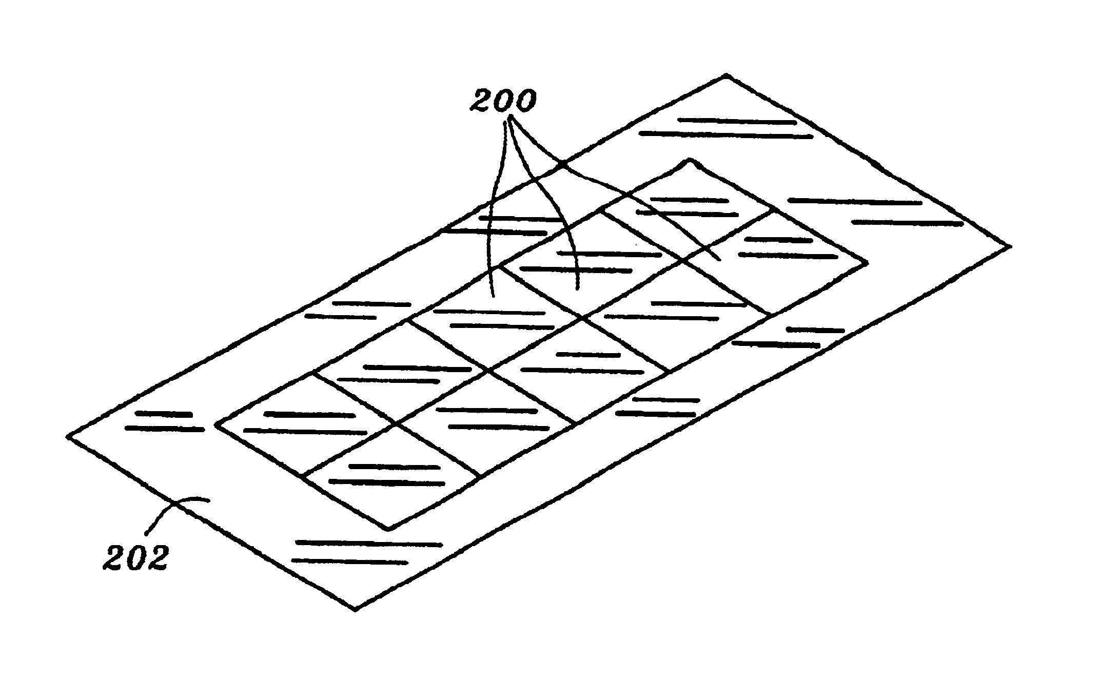
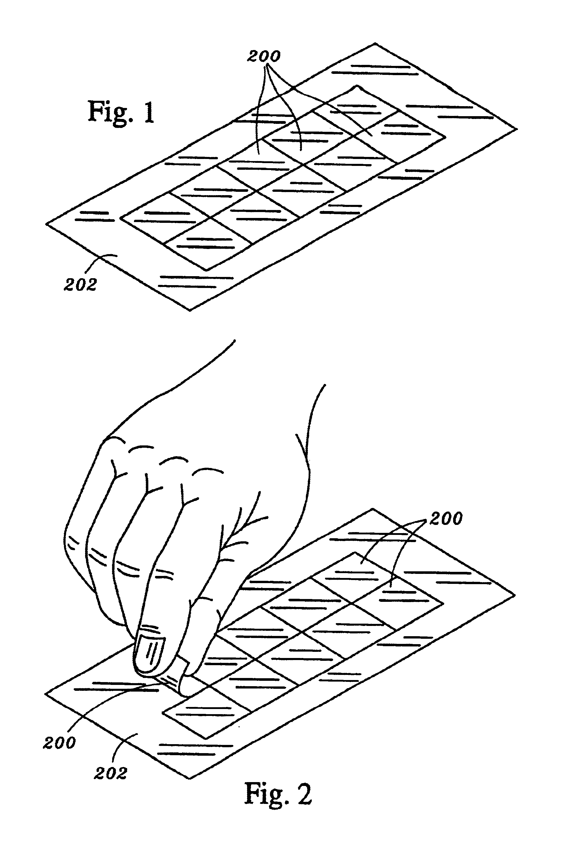
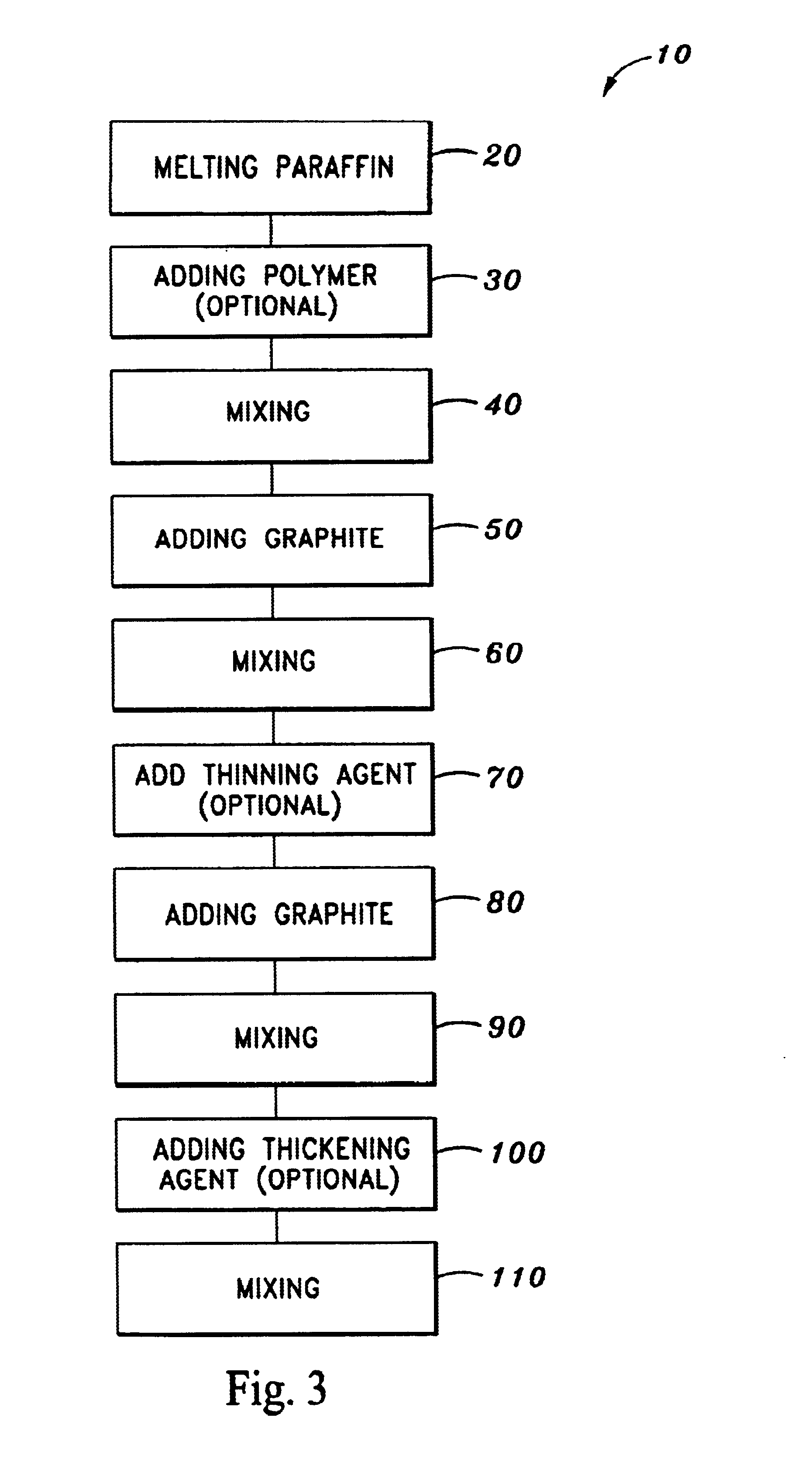

Image

  • Phase change thermal interface composition having induced bonding property
  • Phase change thermal interface composition having induced bonding property
  • Phase change thermal interface composition having induced bonding property

Examples


Embodiment Construction

The detailed description set forth below in connection with the appended drawings is intended merely as a description of the invention, and is not intended to represent the only form in which the present invention may be constructed or utilized. The description sets forth the functions and sequence of steps for construction and implementation of the invention in connection with the illustrated embodiments. It is to be understood, however, that the same or equivalent functions and sequences may be accomplished by different embodiments that are also intended to be encompassed within the spirit and scope of the invention.

The composition of the present invention comprises a durable wax-like, thermally conductive interface compound whose purpose is to complete a thermally conductive path from a heated element to a heat sink, that is exceptionally more durable, and possess better re-flow properties than prior art compositions. In this regard, the use of heat conducting materials to transf...


PUM

PropertyMeasurementUnit
thicknessaaaaaaaaaa
thicknessaaaaaaaaaa
temperatureaaaaaaaaaa

Abstract

An improved, more durable heat conductive composition for transferring heat from a heat-dissipating component to a heat dissipater and method of producing the same. The composition preferably comprises a base consisting of paraffin and, optionally, paraffin and petrolatun having electrically-conductive particles suspended therein, which preferably include graphite diamond, or elemental metals such as silver. In the preferred embodiment, the composition further includes a resin polymer to increase durability. The composition is formulated to be solid in the range of normal room temperatures, but liquify once subjected to temperatures just below the range at which heat generating electronic semi conductor devices typically operate. The present invention further comprises processes for packaging the compositions of the present invention, as well as applying the heat conductive composition to an interface between a heat-dissipating component and a heat sink.

Description

BACKGROUND OF THE INVENTIONMethods and materials for transferring beat at the interface between a heat-dissipating component, which typically includes various electronic components in semi-conductor devices, to an external heat dissipator or heat sink are well-known in the art. In this regard, the electronic components generate substantial heat which can cause the component to fail catastrophically. Even to the extent the component does not fail, such elevated temperatures can and frequently do affect the component's electrical characteristics and can cause intermittent or permanent changes. Indeed, the life of an electronic component is directly related to its operating temperature, and a temperature rise of so much as 10° C. can reduce the component's life by 50%. On the other hand, a corresponding decrease in 10° C. can increase a component's life by 100%.According to contemporary methodology, the typical solution to such heat dissipation problems is to provide an external heat d...

Claims


Application Information

Patent Timeline
Patent Type & Authority Patents(United States)
IPC IPC(8): C08K3/04C08K5/01C08K3/00C08K5/00H01L23/427H01L23/34C08L91/00C09K5/06H01L23/373
CPCC08K3/04C08K5/01C09K5/063H01L23/4275C08L23/08H01L2924/0002H01L2924/00C09D5/26
Inventor FREULER, RAYMOND G.FLYNN, GARY E.RAUCH, ROBERT A.
Owner LOCTITE
Why Eureka
Try Eureka